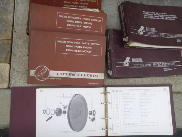
Contents: 1. Tomos Parts Grid 2
Contents: 2. Grid Columns
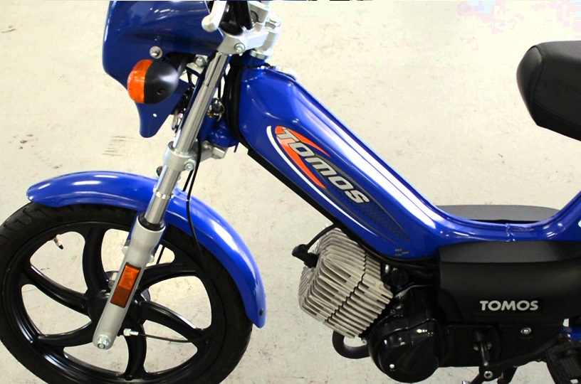
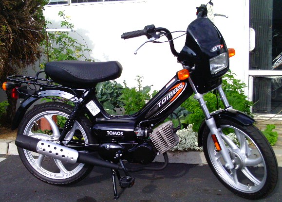
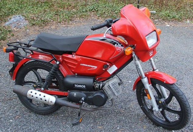
Contents: 3. Bike Colors
Contents: 4. Part Colors
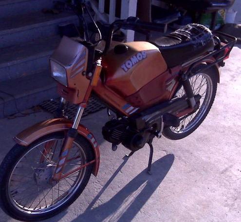
1. Tomos Parts Grid 2
See Tomos Parts Grid 1 for the first 80% of parts, and explanations. This is only the last 20%.
| | | | | | | | | | | | | |
|---|
| Myrons Mopeds presents: | | Tomos Parts Applications (USA models 1975-2013) | | | | | | | | | | | |
| 240225 to 242314 (3h) | Grid Tool 2018 |  |  | 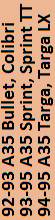 | 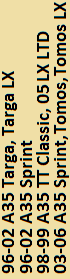 | 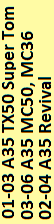 |  |  |  |  |  |  |  |
| part # | enhanced description | | A3 | A35 | A35 | A35 | A55 | A55 | A55 | A55 | A55 | A55 | A55 |
| 240225 | spacer-see also 227485 | oo | ooo | ooo | oooo | ●oo | oo | oo | ooo | ooo | ooo | ooo | ooo |
| 241091 | Main harness 08-on Spr,ST,LX | oo | ooo | ooo | oooo | ooo | oo | oo | ooo | ooo | o●● | o●● | o●● |
| 241092 | Power harn 08-on Sprint,ST,LX | oo | ooo | ooo | oooo | ooo | oo | oo | ooo | ooo | o●● | o●● | o●● |
| 241099 | Grips L & R for 2008-on TBS | oo | ooo | ooo | oooo | ooo | oo | ●● | o●● | o●● | ooo | o●● | o●● |
| 242001 | Handlebar (Super Tom only) | oo | ooo | ooo | oooo | ●oo | oo | oo | ooo | ooo | ooo | ooo | ooo |
| 242002BLK | Lamp holder RH 03-06 black | oo | ooo | ooo | ooo● | ooo | oo | oo | ooo | ooo | ooo | ooo | ooo |
| 242002GRN | Lamp holder RH 03-06 green | oo | ooo | ooo | ooo● | ooo | oo | oo | ooo | ooo | ooo | ooo | ooo |
| 242002METBLU | Lamp holder RH 03-06 met blue | oo | ooo | ooo | ooo● | ooo | oo | oo | ooo | ooo | ooo | ooo | ooo |
| 242002PUR | Lamp holder RH 03-06 purple | oo | ooo | ooo | ooo● | ooo | oo | oo | ooo | ooo | ooo | ooo | ooo |
| 242002RED | Lamp holder RH 03-06 red | oo | ooo | ooo | ooo● | ooo | oo | oo | ooo | ooo | ooo | ooo | ooo |
| 242002ULTBLU | Lamp holder RH 03-06 ultra blu | oo | ooo | ooo | ooo● | ooo | oo | oo | ooo | ooo | ooo | ooo | ooo |
| 242002WHT | Lamp holder RH 03-06 white | oo | ooo | ooo | ooo● | ooo | oo | oo | ooo | ooo | ooo | ooo | ooo |
| 242003BLK | Lamp holder LH 03-06 black | oo | ooo | ooo | ooo● | ooo | oo | oo | ooo | ooo | ooo | ooo | ooo |
| 242003GRN | Lamp holder LH 03-06 green NA | oo | ooo | ooo | ooo● | ooo | oo | oo | ooo | ooo | ooo | ooo | ooo |
| 242003METBLU | Lamp holder LH 03-06 met blue | oo | ooo | ooo | ooo● | ooo | oo | oo | ooo | ooo | ooo | ooo | ooo |
| 242003PUR | Lamp holder LH 03-06 purple | oo | ooo | ooo | ooo● | ooo | oo | oo | ooo | ooo | ooo | ooo | ooo |
| 242003RED | Lamp holder LH 03-06 red | oo | ooo | ooo | ooo● | ooo | oo | oo | ooo | ooo | ooo | ooo | ooo |
| 242003ULTBLU | Lamp holder LH 03-06 ultra blu | oo | ooo | ooo | ooo● | ooo | oo | oo | ooo | ooo | ooo | ooo | ooo |
| 242003WHT | Lamp holder LH 03-06 white | oo | ooo | ooo | ooo● | ooo | oo | oo | ooo | ooo | ooo | ooo | ooo |
| 242003YEL05 | Lamp holder LH 03-06 yellow05 | oo | ooo | ooo | ooo● | ooo | oo | oo | ooo | ooo | ooo | ooo | ooo |
| 242005YEL05 | Upper yoke painted Yellow 05 | oo | ooo | ooo | ooo● | ooo | oo | oo | ooo | ooo | ooo | ooo | ooo |
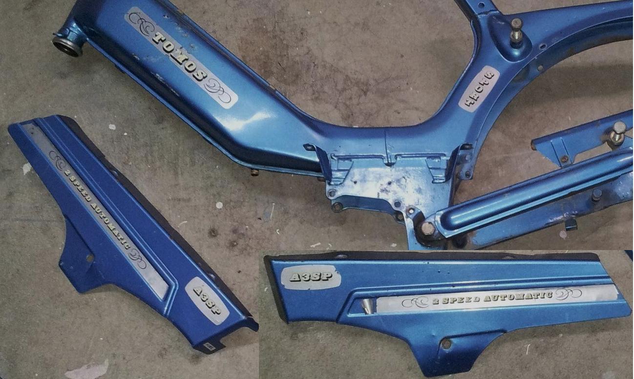
| 242028 | Frame painted - Tomos A35 | oo | ooo | ooo | ooo● | ooo | oo | oo | ooo | ooo | ooo | ooo | ooo |
| 242032 | Seat support painted | oo | ooo | ooo | oooo | oo● | oo | oo | ooo | ●●● | ooo | ooo | ooo |
| 242033 | Support bracket Rev kick black | oo | ooo | ooo | oooo | oo● | oo | oo | ooo | ●●● | ooo | ooo | ooo |
| 242034 | Turn signals holder (chrome) | oo | ooo | ooo | oooo | oo● | oo | oo | ●●● | ●●● | ooo | ooo | ooo |
| 242035 | Headlight holder (black) | oo | ooo | ooo | oooo | oo● | oo | oo | ●●● | ●●● | ooo | ooo | ooo |
| 242036 | Baffle tube - chrome | oo | ooo | ooo | oooo | oo● | oo | oo | ooo | ooo | ooo | ooo | ooo |
| 242038 | Frame painted - Tomos LX - new | oo | ooo | ooo | ooo● | ooo | oo | oo | ooo | ooo | ●●● | ooo | ooo |
| 242039BLK | Eng cover LH 03-06 Sprint blac | oo | ooo | ooo | ooo● | ooo | oo | oo | ooo | ooo | ooo | ooo | ooo |
| 242040 | Frame painted - Sprint - new | oo | ooo | ooo | ooo● | ooo | oo | oo | ooo | ooo | ooo | ooo | ●●● |
| 242042 | Handlebar Revival&Arrow | oo | ooo | ooo | oooo | oo● | ●o | oo | ooo | ●●● | ooo | ooo | ooo |
| 242045 | Faux cap (chrome) | oo | ooo | ooo | oooo | oo● | oo | oo | ooo | ●●● | ooo | ooo | ooo |
| 242046 | Protector painted (black)NLA | oo | ooo | ooo | oooo | oo● | oo | ●● | ●●● | ●●● | ooo | ooo | ooo |
| 242051BLK | Engine cover LH 03-06 black | oo | ooo | ooo | ooo● | ooo | oo | oo | ooo | ooo | ooo | ooo | ooo |
| 242051GRN | Engine cover LH 03-06 green | oo | ooo | ooo | ooo● | ooo | oo | oo | ooo | ooo | ooo | ooo | ooo |
| 242051RED | Engine cover LH 03-06 red | oo | ooo | ooo | ooo● | ooo | oo | oo | ooo | ooo | ooo | ooo | ooo |
| 242051SIL | Engine cover LH 03-06 silver | oo | ooo | ooo | ooo● | ooo | oo | oo | ooo | ooo | ooo | ooo | ooo |
| 242051ULTBLU | Engine cover LH 03-06 ultra bl | oo | ooo | ooo | ooo● | ooo | oo | oo | ooo | ooo | ooo | ooo | ooo |
| 242051YEL05 | Engine cover LH 03-06 yellow05 | oo | ooo | ooo | ooo● | ooo | oo | oo | ooo | ooo | ooo | ooo | ooo |
| 242055BLK | Front fender 07-on black | oo | ooo | ooo | oooo | ooo | oo | oo | ooo | ooo | ●●● | ●●● | ●●● |
| 242055METBLU | Front fender 07-on met blue | oo | ooo | ooo | oooo | ooo | oo | oo | ooo | ooo | ooo | ooo | ooo |
| 242055RED | Front fender 07-on red | oo | ooo | ooo | oooo | ooo | oo | oo | ooo | ooo | ●●● | ●●● | ooo |
| 242055SIL | Front fender 07-on silver | oo | ooo | ooo | oooo | ooo | oo | oo | ooo | ooo | ●●o | ooo | ●●● |
| 242055ULTBLU | Front fender 07-on ultra blue | oo | ooo | ooo | oooo | ooo | oo | oo | ooo | ooo | ●●● | ●●● | ooo |
| 242055WHT | Front fender 07-on white | oo | ooo | ooo | oooo | ooo | oo | oo | ooo | ooo | ●●● | ooo | ooo |
| 242056BLK | Front fender holder Black | oo | ooo | ooo | oooo | ooo | oo | oo | ooo | ooo | ●●● | ●●● | ●●● |
| 242056SIL | Front fender holder Silver | oo | ooo | ooo | oooo | ooo | oo | oo | ooo | ooo | ●●o | ooo | ●●● |
| 242056WHT | Front fender holder White | oo | ooo | ooo | oooo | ooo | oo | oo | ooo | ooo | ●●● | ooo | ooo |
| 242070BLU | Frame painted Revival Blue | oo | ooo | ooo | oooo | oo● | oo | oo | ooo | ooo | ooo | ooo | ooo |
| 242070RED | Frame painted Revival Red | oo | ooo | ooo | oooo | oo● | oo | oo | ooo | ●●● | ooo | ooo | ooo |
| 242071BLU | Swing arm Rev/Smate blue N/A | oo | ooo | ooo | oooo | ooo | oo | oo | ooo | ●●● | ooo | ooo | ooo |
| 242071RED | Swing arm Rev/Smate Rev red | oo | ooo | ooo | oooo | ooo | oo | oo | ooo | ●●● | ooo | ooo | ooo |
| 242071SIL | Swing arm Rev/Smate silver | oo | ooo | ooo | oooo | ooo | oo | ●● | ●●● | ●●● | ooo | ooo | ooo |
| 242072 | Luggage carrier - chrome | oo | ooo | ooo | oooo | oo● | oo | oo | ooo | ooo | ooo | ooo | ooo |
| 242074BLK | Faux tank painted RH Black | oo | ooo | ooo | oooo | ooo | oo | oo | ooo | ●●o | ooo | ooo | ooo |
| 242074BLU | Faux tank painted RH Blue | oo | ooo | ooo | oooo | oo● | oo | oo | ooo | ●●● | ooo | ooo | ooo |
| 242074RED | Faux tank painted RH Red | oo | ooo | ooo | oooo | oo● | oo | oo | ooo | ●●o | ooo | ooo | ooo |
| 242075BLK | Faux tank painted LH Black | oo | ooo | ooo | oooo | ooo | oo | oo | ooo | ●●o | ooo | ooo | ooo |
| 242075BLU | Faux tank painted LH Blue | oo | ooo | ooo | oooo | oo● | oo | oo | ooo | ●●● | ooo | ooo | ooo |
| 242075RED | Faux tank painted LH Red | oo | ooo | ooo | oooo | oo● | oo | oo | ooo | ●●o | ooo | ooo | ooo |
| 242075 | Faux tank painted (LH side) | oo | ooo | ooo | oooo | oo● | oo | oo | ooo | ●●● | ooo | ooo | ooo |
| 242077 | Battery holder | oo | ooo | ooo | oooo | oo● | oo | oo | ooo | ●●● | ooo | ooo | ooo |
| 242078 | Engine protector (chrome) | oo | ooo | ooo | oooo | oo● | oo | oo | ooo | ●●● | ooo | ooo | ooo |
| 242081 | Speedometer housing (bottom on | oo | ooo | ooo | oooo | oo● | oo | oo | ●●● | ●●● | ooo | ooo | ooo |
| 242082 | Speedometer holder | oo | ooo | ooo | oooo | oo● | oo | oo | ●●● | ●●● | ooo | ooo | ooo |
| 242083BLK | RH side cover kick (matte blk) | oo | ooo | ooo | oooo | ooo | ●● | ●● | ooo | ooo | ●●● | ●●● | ●●● |
| 242083CHR | RH side cover kick (Chrome) | oo | ooo | ooo | oooo | ooo | oo | oo | ●●● | ●●● | ooo | ooo | ooo |
| 242083SBLK | RH side cover kick (shiny blk) | oo | ooo | ooo | oooo | ooo | oo | ●● | ooo | ooo | ●●● | ●●● | ●●● |
| 242084BLK | LH side cover (matte black) | oo | ooo | ooo | oooo | ooo | ●● | ●● | ooo | ooo | ●●● | ●●● | ●●● |
| 242084CHR | LH side cover (Chrome) | oo | ooo | ooo | oooo | ooo | oo | oo | ●●● | ●●● | ooo | ooo | ooo |
| 242084SBLK | LH side cover (Shiny Black) | oo | ooo | ooo | oooo | ooo | oo | ●● | ooo | ooo | ●●● | ●●● | ●●● |
| 242085 | Chain guard (chrome) | oo | ooo | ooo | oooo | oo● | oo | oo | ●●● | ●●● | ooo | ooo | ooo |
| 242086 | RH reflector panel (chrome) | oo | ooo | ooo | oooo | oo● | oo | oo | ●●● | ●●● | ooo | ooo | ooo |
| 242087 | LH reflector panel (chrome) | oo | ooo | ooo | oooo | oo● | oo | oo | ●●● | ●●● | ooo | ooo | ooo |
| 242088BLK | Front fender Revival TS Black | oo | ooo | ooo | oooo | ooo | oo | oo | ooo | ●●o | ooo | ooo | ooo |
| 242088BLU | Front fender Revival Blue | oo | ooo | ooo | oooo | oo● | oo | oo | ooo | ●●● | ooo | ooo | ooo |
| 242088RED | Front fender Revival Red | oo | ooo | ooo | oooo | oo● | oo | oo | ooo | ●●o | ooo | ooo | ooo |
| 242089BLU | Rear fender Revival blue | oo | ooo | ooo | oooo | oo● | oo | oo | ooo | ●●● | ooo | ooo | ooo |
| 242089RED | Rear fender Revival red | oo | ooo | ooo | oooo | oo● | oo | oo | ooo | ●●o | ooo | ooo | ooo |
| 242090 | Tail light holder (black plast | oo | ooo | ooo | oooo | oo● | oo | oo | ooo | ●●● | ooo | ooo | ooo |
| 242092 | Swing arm painted | oo | ooo | ooo | oooo | oo● | oo | oo | ooo | ooo | ooo | ooo | ooo |
| 242093 | Support bracket Rev pedal blac | oo | ooo | ooo | oooo | oo● | oo | oo | ooo | ●●● | ooo | ooo | ooo |
| 242094BLK | RH side cover pedal (matte blk | oo | ooo | ooo | oooo | ooo | ●● | ●● | ooo | ooo | ●●● | ●●● | ●●● |
| 242094CHR | RH side cover pedal (Chrome) | oo | ooo | ooo | oooo | ooo | oo | oo | ooo | ●●● | ooo | ooo | ooo |
| 242094SBLK | RH side cover pedal (shiny blk | oo | ooo | ooo | oooo | ooo | oo | ●● | ooo | ooo | ●●● | ●●● | ●●● |
| 242095 | Horn cover (chrome) | oo | ooo | ooo | oooo | oo● | oo | oo | ooo | ooo | ooo | ooo | ooo |
| 242097 | Kickstand(black)*also 229408* | oo | ooo | ooo | oooo | oo● | oo | ●● | ●●● | ●●● | ooo | ooo | ooo |
| 242098 | Spdo housing black NO ind lite | oo | ooo | ooo | oooo | ooo | oo | oo | ooo | ooo | ooo | ooo | ooo |
| 242102 | Frame paited MC line | oo | ooo | ooo | oooo | o●o | oo | oo | ooo | ooo | ooo | ooo | ooo |
| 242103 | Swing arm painted MC 50 | oo | ooo | ooo | oooo | o●o | oo | oo | ooo | ooo | ooo | ooo | ooo |
| 242104 | Kickstand MC 50 Junior | oo | ooo | ooo | oooo | o●o | oo | oo | ooo | ooo | ooo | ooo | ooo |
| 242105 | Handlebar MC36&MC50JR | oo | ooo | ooo | oooo | o●o | oo | oo | ooo | ooo | ooo | ooo | ooo |
| 242106 | Swing arm painted MC 36 | oo | ooo | ooo | oooo | o●o | oo | oo | ooo | ooo | ooo | ooo | ooo |
| 242122 | Kickstand MC 50 Sr & S.Pro-OB | oo | ooo | ooo | oooo | o●o | oo | oo | ooo | ooo | ooo | ooo | ooo |
| 242123 | Handlebar | o● | ooo | ooo | oooo | o●o | oo | oo | ooo | ooo | ooo | ooo | ooo |
| 242124 | Swing arm painted MC 50 Jr | oo | ooo | ooo | oooo | o●o | oo | oo | ooo | ooo | ooo | ooo | ooo |
| 242125 | Kickstand MC 36 | oo | ooo | ooo | oooo | o●o | oo | oo | ooo | ooo | ooo | ooo | ooo |
| 242128BLK | F fender stay 03-06 black | oo | ooo | ooo | ooo● | ooo | oo | oo | ooo | ooo | ooo | ooo | ooo |
| 242128GRN | F fender stay 03-06 teal green | oo | ooo | ooo | ooo● | ooo | oo | oo | ooo | ooo | ooo | ooo | ooo |
| 242128RED | F fender stay 03-06 red | oo | ooo | ooo | ooo● | ooo | oo | oo | ooo | ooo | ooo | ooo | ooo |
| 242128ULTBLU | F fender stay 03-06 ultra blue | oo | ooo | ooo | ooo● | ooo | oo | oo | ooo | ooo | ooo | ooo | ooo |
| 242128YEL05 | F fender stay 03-06 yellow 05 | oo | ooo | ooo | ooo● | ooo | oo | oo | ooo | ooo | ooo | ooo | ooo |
| 242129BLK | F fender holder 03-06 black | oo | ooo | ooo | ooo● | ooo | oo | oo | ooo | ooo | ooo | ooo | ooo |
| 242129GRN | F fender holder 03-06 teal gre | oo | ooo | ooo | ooo● | ooo | oo | oo | ooo | ooo | ooo | ooo | ooo |
| 242129RED | F fender holder 03-06 red | oo | ooo | ooo | ooo● | ooo | oo | oo | ooo | ooo | ooo | ooo | ooo |
| 242129ULTBLU | F fender holder 03-06 ultra bl | oo | ooo | ooo | ooo● | ooo | oo | oo | ooo | ooo | ooo | ooo | ooo |
| 242129YEL05 | F fender holder 03-06 yellow | oo | ooo | ooo | ooo● | ooo | oo | oo | ooo | ooo | ooo | ooo | ooo |
| 242130BLK | Front fender 03-06 black | oo | ooo | ooo | ooo● | ooo | oo | oo | ooo | ooo | ooo | ooo | ooo |
| 242130GRN | Front fender 03-06 teal green | oo | ooo | ooo | ooo● | ooo | oo | oo | ooo | ooo | ooo | ooo | ooo |
| 242130RED | Front fender 03-06 red | oo | ooo | ooo | ooo● | ooo | oo | oo | ooo | ooo | ooo | ooo | ooo |
| 242130SIL | Front fender 03-06 silver | oo | ooo | ooo | ooo● | ooo | oo | oo | ooo | ooo | ooo | ooo | ooo |
| 242130ULTBLU | Front fender 03-06 ultra blue | oo | ooo | ooo | ooo● | ooo | oo | oo | ooo | ooo | ooo | ooo | ooo |
| 242130YEL05 | Front fender 03-06 yellow-05 | oo | ooo | ooo | ooo● | ooo | oo | oo | ooo | ooo | ooo | ooo | ooo |
| 242133 | Luggage carrier | oo | ooo | ooo | oooo | ooo | oo | oo | ooo | ooo | ●●● | ●●● | ooo |
| 242147 | Luggage rack Revival TS | oo | ooo | ooo | oooo | ooo | oo | oo | ooo | ooo | ooo | ooo | ooo |
| 242154BLK | Front fender Arrow Black | oo | ooo | ooo | oooo | ooo | ●● | oo | ooo | ooo | ooo | ooo | ooo |
| 242154RED | Front fender Arrow Red | oo | ooo | ooo | oooo | ooo | ●o | oo | ooo | ooo | ooo | ooo | ooo |
| 242155BLK | Rear fender Arrow Black-OB | oo | ooo | ooo | oooo | ooo | ●o | oo | ooo | ooo | ooo | ooo | ooo |
| 242155RED | Rear fender Arrow red | oo | ooo | ooo | oooo | ooo | ●o | oo | ooo | ooo | ooo | ooo | ooo |
| 242156 | REAR FENDER ARROW BLA | oo | ooo | ooo | oooo | ooo | oo | oo | ooo | ooo | ooo | ooo | ooo |
| 242157 | Frame for 05 Arrow silver | oo | ooo | ooo | oooo | ooo | ●o | oo | ooo | ooo | ooo | ooo | ooo |
| 242158 | Swing arm painted red/black | oo | ooo | ooo | oooo | ooo | ●● | oo | ooo | ooo | ooo | ooo | ooo |
| 242159 | Rear wheel holder | oo | ooo | ooo | oooo | ooo | ●● | oo | ooo | ooo | ooo | ooo | ooo |
| 242160 | Kickstand (black) see 229094 | oo | ooo | ooo | oooo | ooo | ●● | oo | ooo | ooo | ooo | ooo | ooo |
| 242161 | SUPPORT BRACKET-NLA | oo | ooo | ooo | oooo | ooo | oo | oo | ooo | ooo | ooo | ooo | ooo |
| 242165BLK | Faux tank paint. RH matte blac | oo | ooo | ooo | oooo | ooo | oo | oo | ●oo | ooo | ooo | ooo | ooo |
| 242165BLU | Faux tank Painted RH BLUE | oo | ooo | ooo | oooo | ooo | oo | ●● | ooo | ooo | ooo | ooo | ooo |
| 242165ORG | Faux tank Painted RH Orange | oo | ooo | ooo | oooo | ooo | oo | oo | ooo | ooo | ooo | ooo | ooo |
| 242165RED | Faux tank Painted RH RED | oo | ooo | ooo | oooo | ooo | oo | ●● | ooo | ooo | ooo | ooo | ooo |
| 242165SBLK | Faux tank paint. RH shiny blac | oo | ooo | ooo | oooo | ooo | oo | ●● | o●o | ooo | ooo | ooo | ooo |
| 242165SIL | Faux tank Painted RH Silver | oo | ooo | ooo | oooo | ooo | oo | oo | ●●● | ooo | ooo | ooo | ooo |
| 242166BLK | Faux tank paint. LH matte blac | oo | ooo | ooo | oooo | ooo | oo | oo | ●oo | ooo | ooo | ooo | ooo |
| 242166BLU | Faux tank Painted LH Blue | oo | ooo | ooo | oooo | ooo | oo | ●● | ooo | ooo | ooo | ooo | ooo |
| 242166ORG | Faux tank Painted LH Orange | oo | ooo | ooo | oooo | ooo | oo | oo | ooo | ooo | ooo | ooo | ooo |
| 242166RED | Faux tank Painted LH Red | oo | ooo | ooo | oooo | ooo | oo | ●● | ooo | ooo | ooo | ooo | ooo |
| 242166SBLK | Faux tank paint. LH shiny blac | oo | ooo | ooo | oooo | ooo | oo | ●● | o●o | ooo | ooo | ooo | ooo |
| 242166SIL | Faux tank Painted LH Silver | oo | ooo | ooo | oooo | ooo | oo | oo | ●●● | ooo | ooo | ooo | ooo |
| 242167BLK | F fender Streetmate matte blac | oo | ooo | ooo | oooo | ooo | oo | oo | ●oo | ooo | ooo | ooo | ooo |
| 242167BLU | Front Fender Streetmate R BLUE | oo | ooo | ooo | oooo | ooo | oo | ●● | ooo | ooo | ooo | ooo | ooo |
| 242167COP | Front Fender Streetmate Copper | oo | ooo | ooo | oooo | ooo | oo | oo | ●●o | ooo | ooo | ooo | ooo |
| 242167RED | Front Fender Streetmate RED | oo | ooo | ooo | oooo | ooo | oo | ●● | ooo | ooo | ooo | ooo | ooo |
| 242167SBLK | F fender Streetmate shiny blac | oo | ooo | ooo | oooo | ooo | oo | ●● | o●o | ooo | ooo | ooo | ooo |
| 242167SIL | Front Fender Streetmate Silver | oo | ooo | ooo | oooo | ooo | oo | oo | ●●● | ooo | ooo | ooo | ooo |
| 242168BLK | R fender Streetmate matte blac | oo | ooo | ooo | oooo | ooo | oo | oo | ●oo | ooo | ooo | ooo | ooo |
| 242168BLU | R fender Streetmate-R blue | oo | ooo | ooo | oooo | ooo | oo | ●● | ooo | ooo | ooo | ooo | ooo |
| 242168ORG | R fender Streetmate orange | oo | ooo | ooo | oooo | ooo | oo | oo | ooo | ooo | ooo | ooo | ooo |
| 242168RED | R fender Streetmate-R red | oo | ooo | ooo | oooo | ooo | oo | ●● | ooo | ooo | ooo | ooo | ooo |
| 242168SBLK | R fender Streetmate shiny blac | oo | ooo | ooo | oooo | ooo | oo | ●● | o●o | ooo | ooo | ooo | ooo |
| 242169BLK | Faux Tank Cover Matte Black | oo | ooo | ooo | oooo | ooo | oo | oo | ●oo | ooo | ooo | ooo | ooo |
| 242169BLU | Faux Tank Cover Painted Blue | oo | ooo | ooo | oooo | ooo | oo | ●● | ooo | ooo | ooo | ooo | ooo |
| 242169COP | Faux Tank Cover Painted Copper | oo | ooo | ooo | oooo | ooo | oo | oo | ●●o | ooo | ooo | ooo | ooo |
| 242169ORG | Faux Tank Cover Painted Orange | oo | ooo | ooo | oooo | ooo | oo | oo | ooo | ooo | ooo | ooo | ooo |
| 242169RED | Faux Tank Cover Painted Red | oo | ooo | ooo | oooo | ooo | oo | ●● | ooo | ooo | ooo | ooo | ooo |
| 242169SIL | Faux Tank Cover Painted SILVER | oo | ooo | ooo | oooo | ooo | oo | oo | ●●● | ooo | ooo | ooo | ooo |
| 242170 | Luggage carrier Streetmate | oo | ooo | ooo | oooo | ooo | oo | oo | ●●● | ooo | ooo | ooo | ooo |
| 242178BLK | Seat frame black Streetmate | oo | ooo | ooo | oooo | ooo | oo | ●● | ●●● | ooo | ooo | ooo | ooo |
| 242194BLK | Lamp holder Arrow R&L black | oo | ooo | ooo | oooo | ooo | ●o | oo | ooo | ooo | ooo | ooo | ooo |
| 242194RED | Lamp holder Arrow R&L red | oo | ooo | ooo | oooo | ooo | ●o | oo | ooo | ooo | ooo | ooo | ooo |
| 242198 | Foot Peg Bracket | oo | ooo | ooo | oooo | ooo | ●o | ●● | ●●● | ooo | o●● | o●● | o●● |
| 242199 | Handlebar black Sprint,ST | oo | ooo | ooo | oooo | ooo | oo | oo | ooo | ooo | o●● | o●● | o●● |
| 242212 | Kickstand MC80 -OB | o● | ooo | ooo | oooo | ooo | oo | oo | ooo | ooo | ooo | ooo | ooo |
| 242224 | Arrow Racing Handlebar | oo | ooo | ooo | oooo | ooo | o● | oo | ooo | ooo | ooo | ooo | ooo |
| 242226BLK | Lamp holder RH ArrowR black | oo | ooo | ooo | oooo | ooo | o● | oo | ooo | ooo | ooo | ooo | ooo |
| 242227BLK | Lamp holder LH ArrowR black | oo | ooo | ooo | oooo | ooo | o● | oo | ooo | ooo | ooo | ooo | ooo |
| 242228 | Bulb holder | oo | ooo | ooo | oooo | ooo | o● | ●● | ooo | ooo | ooo | ooo | ooo |
| 242241RED | Frame- ST - painted RED | oo | ooo | ooo | oooo | ooo | oo | oo | ooo | ooo | ooo | ●●● | ooo |
| 242247RED | Frame- LX - painted RED | oo | ooo | ooo | oooo | ooo | oo | oo | ooo | ooo | ●●● | ooo | ooo |
| 242256 | Cap | oo | ooo | ooo | oooo | ooo | oo | oo | ooo | ooo | ooo | ooo | ooo |
| 242260BLK | Front wheel 12" Arrow black | oo | ooo | ooo | oooo | ooo | oo | oo | ooo | ooo | ooo | ooo | ooo |
| 242261BLK | Rear wheel 12" Arrow black | oo | ooo | ooo | oooo | ooo | o● | oo | ooo | ooo | ooo | ooo | ooo |
| 242264BLK | Rear Fender Arrow-R black | oo | ooo | ooo | oooo | ooo | o● | oo | ooo | ooo | ooo | ooo | ooo |
| 242264RED | Rear Fender Arrow-R red | oo | ooo | ooo | oooo | ooo | o● | oo | ooo | ooo | ooo | ooo | ooo |
| 242264YEL | Rear Fender Arrow-R yellow | oo | ooo | ooo | oooo | ooo | o● | oo | ooo | ooo | ooo | ooo | ooo |
| 242265SIL | Luggage Plate Arrow-R silver | oo | ooo | ooo | oooo | ooo | o● | oo | ooo | ooo | ooo | ooo | ooo |
| 242266 | Wire Harness Protector | oo | ooo | ooo | oooo | ooo | o● | oo | ooo | ooo | ooo | ooo | ooo |
| 242268 | Seat latch Arrow-R N/A | oo | ooo | ooo | oooo | ooo | o● | oo | ooo | ooo | ooo | ooo | ooo |
| 242269 | SEAT HOLDER-NLA | oo | ooo | ooo | oooo | ooo | oo | oo | ooo | ooo | ooo | ooo | ooo |
| 242271BLK | Fairing SmR/ArR matte black | oo | ooo | ooo | oooo | ooo | o● | oo | ooo | ooo | ooo | ooo | ooo |
| 242271BLU | Fairing SmR/ArrowR blue | oo | ooo | ooo | oooo | ooo | oo | ●● | ooo | ooo | ooo | ooo | ooo |
| 242271ORG | Fairing SmR/ArrowR orange | oo | ooo | ooo | oooo | ooo | o● | oo | ooo | ooo | ooo | ooo | ooo |
| 242271RED | Fairing SmR/ArrowR red | oo | ooo | ooo | oooo | ooo | o● | ●● | ooo | ooo | ooo | ooo | ooo |
| 242271SBLK | Fairing SmR/ArR shiny black | oo | ooo | ooo | oooo | ooo | o● | ●● | ooo | ooo | ooo | ooo | ooo |
| 242271SIL | Fairing SmR/ArrowR silver | oo | ooo | ooo | oooo | ooo | oo | ●● | ooo | ooo | ooo | ooo | ooo |
| 242271YEL | Fairing SmR/ArrowR yellow | oo | ooo | ooo | oooo | ooo | o● | oo | ooo | ooo | ooo | ooo | ooo |
| 242272BLK | Rear Fender Arrow-R black | oo | ooo | ooo | oooo | ooo | o● | oo | ooo | ooo | ooo | ooo | ooo |
| 242273ORG | R fender F holder Arr-R orange | oo | ooo | ooo | oooo | ooo | oo | oo | ooo | ooo | ooo | ooo | ooo |
| 242273YEL | R fender F holder Arr-R yellow | oo | ooo | ooo | oooo | ooo | oo | oo | ooo | ooo | ooo | ooo | ooo |
| 242274ORG | Upper R fend brace ArrR orange | oo | ooo | ooo | oooo | ooo | o● | oo | ooo | ooo | ooo | ooo | ooo |
| 242275ORG | Lower R fend brace ArrR orange | oo | ooo | ooo | oooo | ooo | o● | oo | ooo | ooo | ooo | ooo | ooo |
| 242275YEL | Lower R fend brace ArrR yellow | oo | ooo | ooo | oooo | ooo | o● | oo | ooo | ooo | ooo | ooo | ooo |
| 242287 | Seat Plate | oo | ooo | ooo | oooo | ooo | oo | oo | ooo | ooo | ooo | ●●● | ●●● |
| 242307 | SMR Handlebar | oo | ooo | ooo | oooo | ooo | oo | oo | ooo | ooo | ooo | ooo | ooo |
| 242314BLK | Swing arm black '08-on | oo | ooo | ooo | oooo | ooo | oo | oo | ooo | ooo | o●● | o●● | o●● |
| 242314RED | Swing arm red '08-on | oo | ooo | ooo | oooo | ooo | oo | oo | ooo | ooo | o●● | o●● | ooo |
| 242314SIL | Swing arm silver '08-on | oo | ooo | ooo | oooo | ooo | oo | oo | ooo | ooo | o●● | ooo | o●● |
| 242314ULTBLU | Swing arm ultblu '08-on | oo | ooo | ooo | oooo | ooo | oo | oo | ooo | ooo | o●● | o●● | ooo |
| | | | | | | | | | | | | |
|---|
| Myrons Mopeds presents: | | Tomos Parts Applications (USA models 1975-2013) | | | | | | | | | | | |
| 243000 to 737784 (3i) | Grid Tool 2018 | | | | | | | | | | | | |
| part # | enhanced description | | A3 | A35 | A35 | A35 | A55 | A55 | A55 | A55 | A55 | A55 | A55 |
| 243000 | Crankcase Cpl. Kick - MC 36 | oo | ooo | ooo | oooo | o●o | oo | oo | ooo | ooo | ooo | ooo | ooo |
| 243001 | Side cover RH MC line | oo | ooo | ooo | oooo | o●o | oo | oo | ooo | ooo | ooo | ooo | ooo |
| 243002 | Side cover LH MC line | oo | ooo | ooo | oooo | o●o | oo | oo | ooo | ooo | ooo | ooo | ooo |
| 243003 | Shield RH MC line | oo | ooo | ooo | oooo | o●o | oo | oo | ooo | ooo | ooo | ooo | ooo |
| 243004 | Shield LH MC line | oo | ooo | ooo | oooo | o●o | oo | oo | ooo | ooo | ooo | ooo | ooo |
| 243005 | Frame cover RH MC line | oo | ooo | ooo | oooo | o●o | oo | oo | ooo | ooo | ooo | ooo | ooo |
| 243006 | Frame cover LH MC line | oo | ooo | ooo | oooo | o●o | oo | oo | ooo | ooo | ooo | ooo | ooo |
| 243007 | Brake lever adjusting screw-OB | o● | ooo | ooo | oooo | o●o | oo | oo | ooo | ooo | ooo | ooo | ooo |
| 243009 | Front caliper assembly Cpl. | oo | ooo | ooo | oooo | o●o | oo | oo | ooo | ooo | ooo | ooo | ooo |
| 243010 | Rear caliper assembly Cpl. | oo | ooo | ooo | oooo | o●o | oo | oo | ooo | ooo | ooo | ooo | ooo |
| 243011 | Brake pad front and/or rear | oo | ooo | ooo | oooo | o●o | oo | oo | ooo | ooo | ooo | ooo | ooo |
| 243012 | Front hyd.brake line | oo | ooo | ooo | oooo | o●o | oo | oo | ooo | ooo | ooo | ooo | ooo |
| 243013 | Rear hydraulic brake line | oo | ooo | ooo | oooo | o●o | oo | oo | ooo | ooo | ooo | ooo | ooo |
| 243014 | Front axle | oo | ooo | ooo | oooo | o●o | oo | oo | ooo | ooo | ooo | ooo | ooo |
| 243015 | Distance bush | oo | ooo | ooo | oooo | o●o | oo | oo | ooo | ooo | ooo | ooo | ooo |
| 243016 | Distance bush set Cpl. | oo | ooo | ooo | oooo | o●o | oo | oo | ooo | ooo | ooo | ooo | ooo |
| 243017 | Brake lever RH with clamp | oo | ooo | ooo | oooo | o●o | oo | oo | ooo | ooo | ooo | ooo | ooo |
| 243018 | Brake lever LH with clamp | oo | ooo | ooo | oooo | o●o | oo | oo | ooo | ooo | ooo | ooo | ooo |
| 243019 | Crown bolt assembly Cpl. | o● | ooo | ooo | oooo | o●o | oo | oo | ooo | ooo | ooo | ooo | ooo |
| 243020 | Lower triple-tree painted | oo | ooo | ooo | oooo | o●o | oo | oo | ooo | ooo | ooo | ooo | ooo |
| 243021 | Upper triple-tree painted | oo | ooo | ooo | oooo | o●o | oo | oo | ooo | ooo | ooo | ooo | ooo |
| 243022 | Handlebar clamp | oo | ooo | ooo | oooo | o●o | oo | oo | ooo | ooo | ooo | ooo | ooo |
| 243023 | RH Fork Cpl. MC 50 Junior | oo | ooo | ooo | oooo | o●o | oo | oo | ooo | ooo | ooo | ooo | ooo |
| 243024 | RH Fork Cpl. MC 50 Senior | oo | ooo | ooo | oooo | o●o | oo | oo | ooo | ooo | ooo | ooo | ooo |
| 243025 | LH Fork Cpl. MC 50 Junior | oo | ooo | ooo | oooo | o●o | oo | oo | ooo | ooo | ooo | ooo | ooo |
| 243026 | LH Fork Cpl. MC 50 Senior | oo | ooo | ooo | oooo | o●o | oo | oo | ooo | ooo | ooo | ooo | ooo |
| 243027 | RH Fork Cpl. MC 36 | oo | ooo | ooo | oooo | o●o | oo | oo | ooo | ooo | ooo | ooo | ooo |
| 243028 | LH Fork Cpl. MC 36 | oo | ooo | ooo | oooo | o●o | oo | oo | ooo | ooo | ooo | ooo | ooo |
| 243029 | Handlebar clamp | oo | ooo | ooo | oooo | o●o | oo | oo | ooo | ooo | ooo | ooo | ooo |
| 243030 | Screw M8 x 70-OB | oo | ooo | ooo | oooo | o●o | oo | oo | ooo | ooo | ooo | ooo | ooo |
| 243031 | Crwn blt ably Cpl. see 243019 | oo | ooo | ooo | oooo | o●o | oo | oo | ooo | ooo | ooo | ooo | ooo |
| 243032 | Lower triple-tree painted | oo | ooo | ooo | oooo | o●o | oo | oo | ooo | ooo | ooo | ooo | ooo |
| 243033 | Upper triple-tree painted-OB | oo | ooo | ooo | oooo | o●o | oo | oo | ooo | ooo | ooo | ooo | ooo |
| 243034 | RH Fork Cpl. | oo | ooo | ooo | oooo | o●o | oo | oo | ooo | ooo | ooo | ooo | ooo |
| 243035 | LH Fork Cpl. | oo | ooo | ooo | oooo | o●o | oo | oo | ooo | ooo | ooo | ooo | ooo |
| 243036 | Rear axle | oo | ooo | ooo | oooo | o●o | oo | oo | ooo | ooo | ooo | ooo | ooo |
| 243037 | Distance bush-NLA | oo | ooo | ooo | oooo | o●o | oo | oo | ooo | ooo | ooo | ooo | ooo |
| 243038 | Distance bush set Cpl.-OB | oo | ooo | ooo | oooo | o●o | oo | oo | ooo | ooo | ooo | ooo | ooo |
| 243039 | Nut M 14 x 1.5 | oo | ooo | ooo | oooo | o●o | oo | oo | ooo | ooo | ooo | ooo | ooo |
| 243040 | Ball bearing 15 x 32 x 9 | oo | ooo | ooo | oooo | o●o | oo | oo | ooo | ooo | ooo | ooo | ooo |
| 243043 | Front brake Cpl. | oo | ooo | ooo | oooo | o●o | oo | oo | ooo | ooo | ooo | ooo | ooo |
| 243044 | Brake shoes pair with spring | oo | ooo | ooo | oooo | o●o | oo | oo | ooo | ooo | ooo | ooo | ooo |
| 243045 | Front axle | oo | ooo | ooo | oooo | o●o | oo | oo | ooo | ooo | ooo | ooo | ooo |
| 243046 | Distance tube-NLA | oo | ooo | ooo | oooo | o●o | oo | oo | ooo | ooo | ooo | ooo | ooo |
| 243047 | Spoke with nipple L=125-OB | oo | ooo | ooo | oooo | o●o | oo | oo | ooo | ooo | ooo | ooo | ooo |
| 243048 | Spoke with nipple L=175-OB | oo | ooo | ooo | oooo | o●o | oo | oo | ooo | ooo | ooo | ooo | ooo |
| 243049 | Spoke with nipple L=120-OB | oo | ooo | ooo | oooo | o●o | oo | oo | ooo | ooo | ooo | ooo | ooo |
| 243050 | Spoke with nipple L=145-OB | oo | ooo | ooo | oooo | o●o | oo | oo | ooo | ooo | ooo | ooo | ooo |
| 243052 | Front axle | oo | ooo | ooo | oooo | o●o | oo | oo | ooo | ooo | ooo | ooo | ooo |
| 243053 | Distance tube L=70-OB | oo | ooo | ooo | oooo | o●o | oo | oo | ooo | ooo | ooo | ooo | ooo |
| 243054 | Distance bush | oo | ooo | ooo | oooo | o●o | oo | oo | ooo | ooo | ooo | ooo | ooo |
| 243055 | Front brake disc | oo | ooo | ooo | oooo | o●o | oo | oo | ooo | ooo | ooo | ooo | ooo |
| 243056 | Brake disc screw-NLA | oo | ooo | ooo | oooo | o●o | oo | oo | ooo | ooo | ooo | ooo | ooo |
| 243059 | Rear brake plate Cpl. | oo | ooo | ooo | oooo | o●o | oo | oo | ooo | ooo | ooo | ooo | ooo |
| 243060 | Sprocket Z=24 | oo | ooo | ooo | oooo | o●o | oo | oo | ooo | ooo | ooo | ooo | ooo |
| 243061 | Sprocket Z=28 | oo | ooo | ooo | oooo | o●o | oo | oo | ooo | ooo | ooo | ooo | ooo |
| 243062 | Locking tab for rear wheel spr | oo | ooo | ooo | oooo | o●o | oo | oo | ooo | ooo | ooo | ooo | ooo |
| 243063 | Screw-NLA | oo | ooo | ooo | oooo | o●o | oo | oo | ooo | ooo | ooo | ooo | ooo |
| 243064 | Rear axle-OB | oo | ooo | ooo | oooo | o●o | oo | oo | ooo | ooo | ooo | ooo | ooo |
| 243065 | Distance bush set Cpl. | oo | ooo | ooo | oooo | o●o | oo | oo | ooo | ooo | ooo | ooo | ooo |
| 243066 | REAR AXLE | oo | ooo | ooo | oooo | o●o | oo | oo | ooo | ooo | ooo | ooo | ooo |
| 243067 | Distance tube | oo | ooo | ooo | oooo | o●o | oo | oo | ooo | ooo | ooo | ooo | ooo |
| 243069 | Holder | oo | ooo | ooo | oooo | o●o | oo | oo | ooo | ooo | ooo | ooo | ooo |
| 243070 | Rear brake disc-OB | oo | ooo | ooo | oooo | o●o | oo | oo | ooo | ooo | ooo | ooo | ooo |
| 243071 | Distance tube | oo | ooo | ooo | oooo | o●o | oo | oo | ooo | ooo | ooo | ooo | ooo |
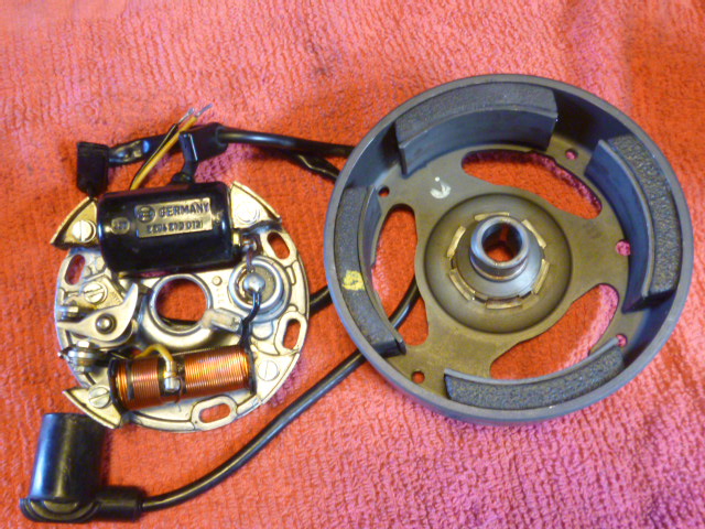
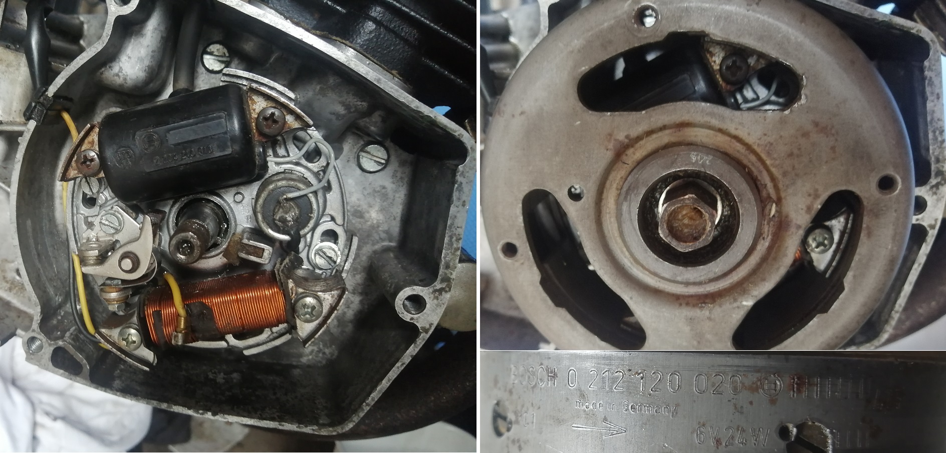
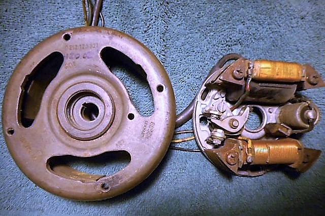
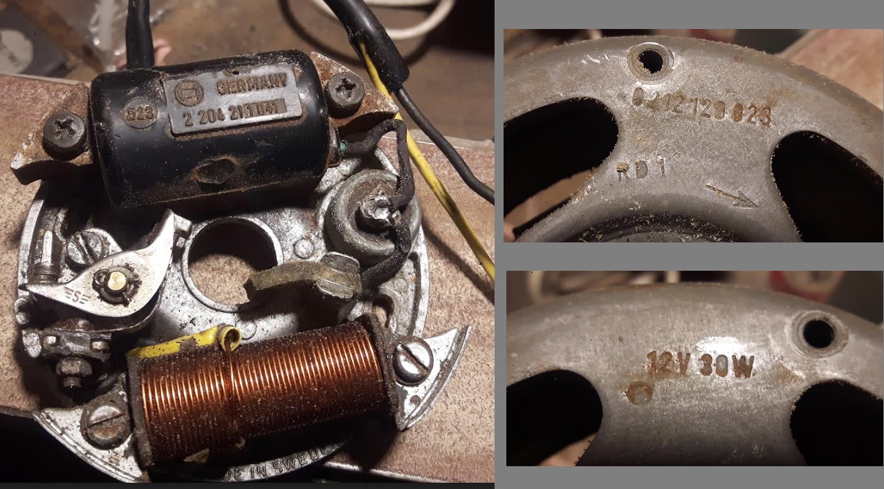
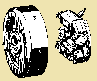
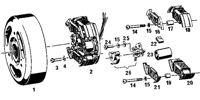
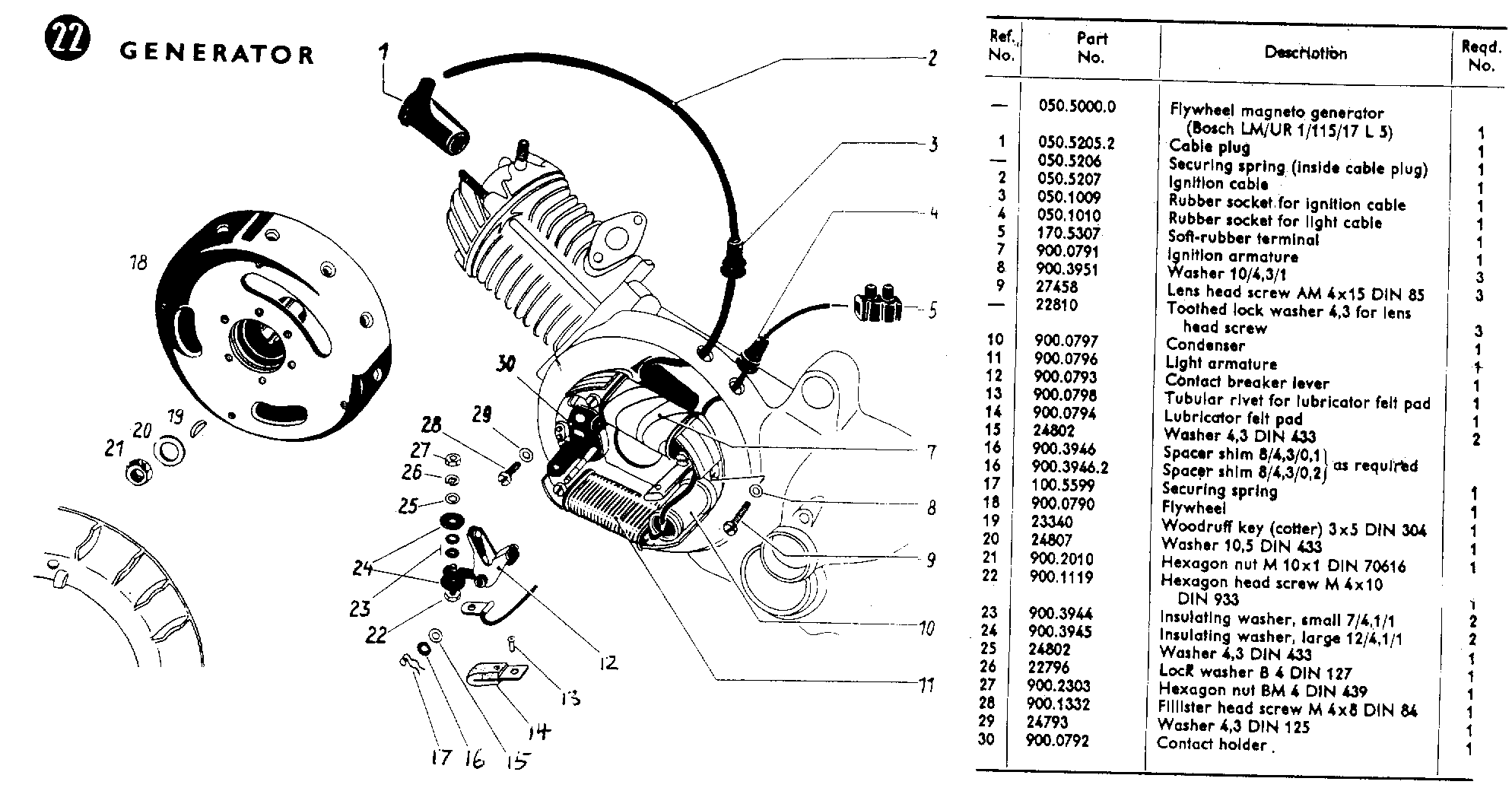
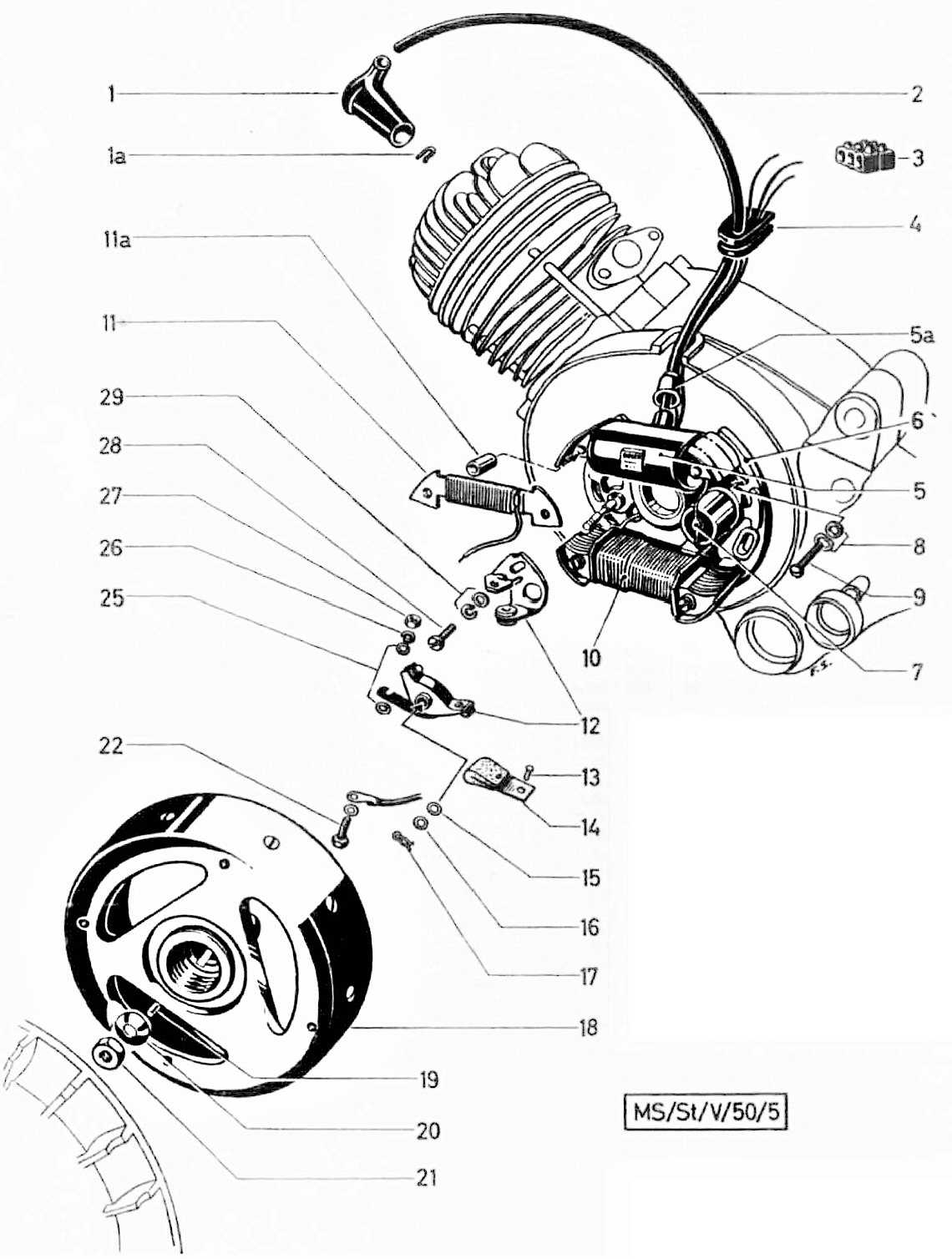
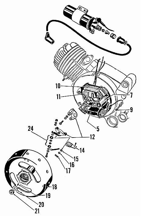
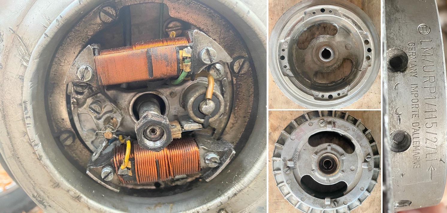
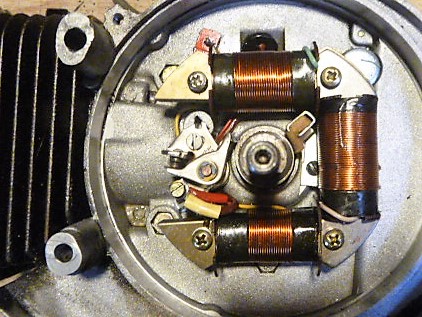
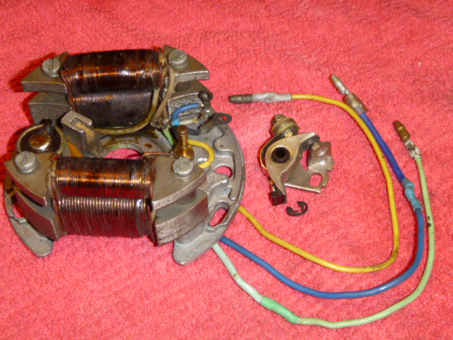
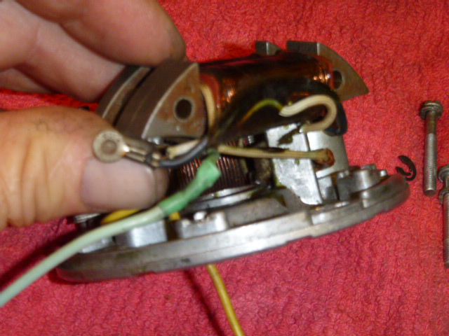
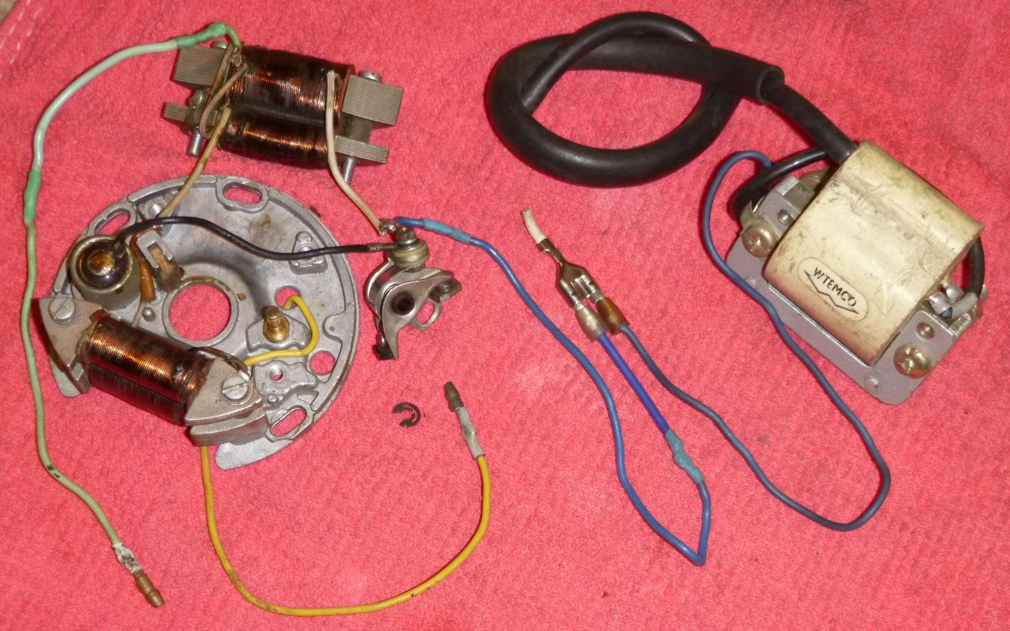
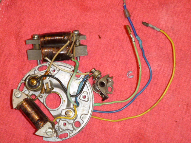
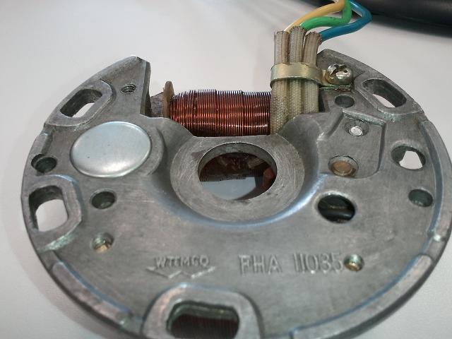
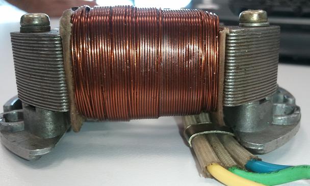
| 243101 | SEE 233720 MAGNETO CPL | oo | ooo | ooo | oooo | ooo | oo | oo | ooo | ooo | ooo | ooo | ooo |
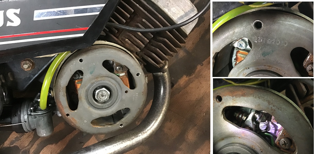
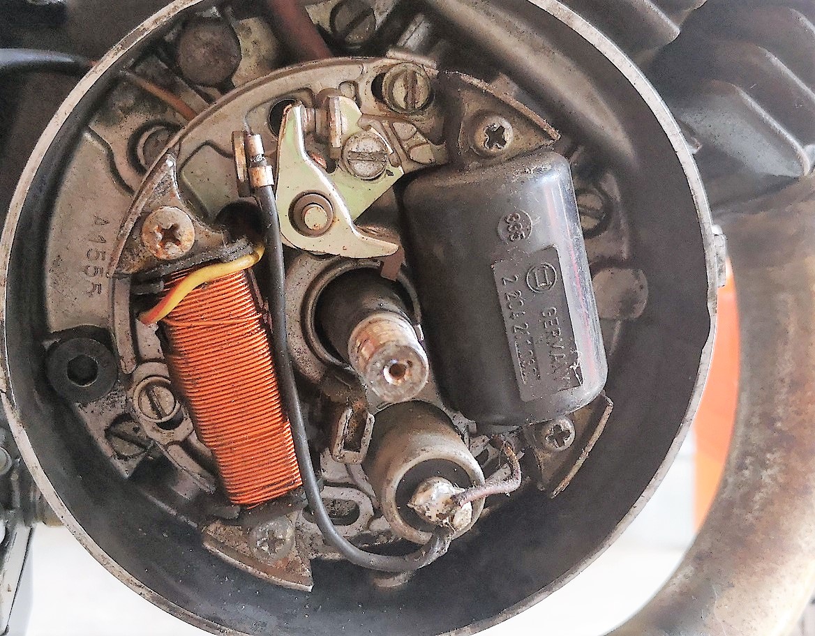
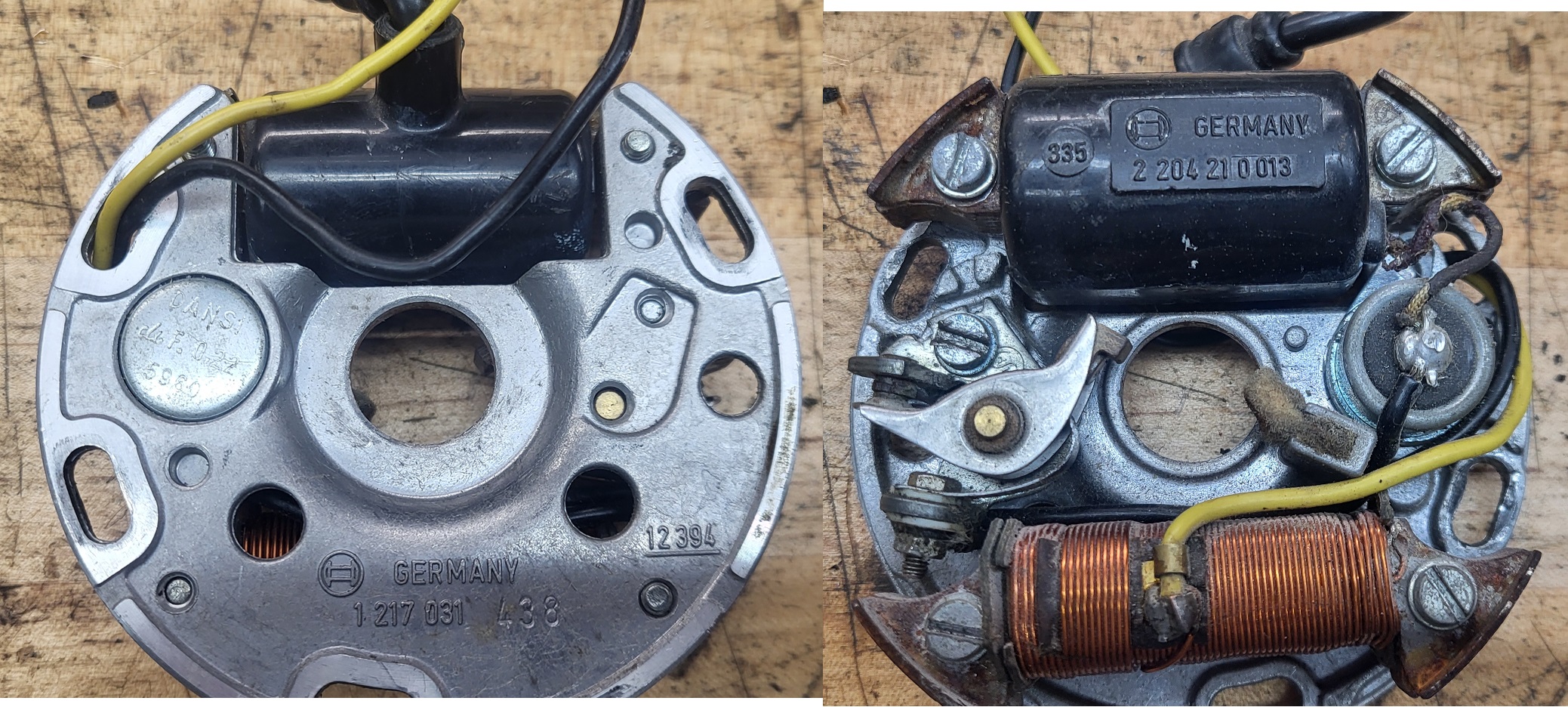
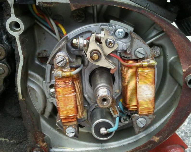
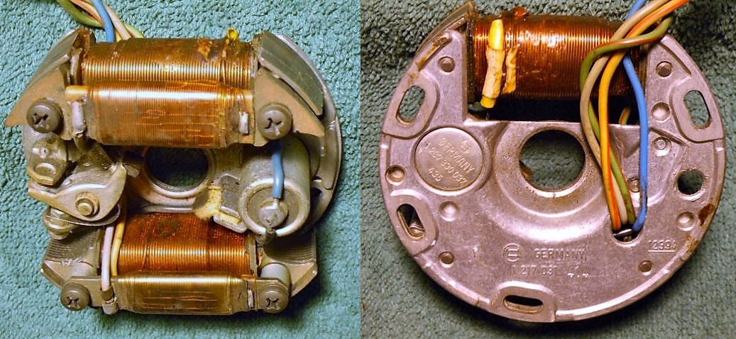
| 243102 | Ignition Pick Up Coil (Pulser) | oo | ooo | ooo | oooo | ooo | ●● | ●● | ●●● | ●●● | ●●● | ●●● | ●●● |
| 243103 | Throttle Slide #40 | oo | ooo | ooo | oooo | ooo | ●● | ●● | ●●● | ●●● | ●●● | ●●● | ●●● |
| 243104 | Throttle Needle A07 | oo | ooo | ooo | oooo | ooo | ●● | ●● | ●●● | ●●● | ●●● | ●●● | ●●● |
| 243106 | Needle Housing 209GA | oo | ooo | ooo | oooo | ooo | ●● | ●● | ●●● | ●●● | ●●● | ●●● | ●●● |
| 243108 | Main Jet 6mm Size 52 | oo | ooo | ooo | oooo | ooo | oo | oo | ooo | ooo | ooo | ooo | ooo |
| 243110 | Idle Jet 4mm Size 29 | oo | ooo | ooo | oooo | ooo | oo | oo | ooo | ooo | ooo | ooo | ooo |
| 243112 | Choke Jet Size ? | oo | ooo | ooo | oooo | ooo | oo | oo | ooo | ooo | ooo | ooo | ooo |
| 243114 | Float | oo | ooo | ooo | oooo | ooo | ●● | ●● | ●●● | ●●● | ●●● | ●●● | ●●● |
| 243115 | Rubber Boot for throttle cable | oo | ooo | ooo | oooo | ooo | ●● | ●● | ●●● | ●●● | ●●● | ●●● | ●●● |
| 243116 | Adjusting Screw with Nut | oo | ooo | ooo | oooo | ooo | ●● | ●● | ●●● | ●●● | ●●● | ●●● | ●●● |
| 243117 | Elbow-NOT AVAILABLE | oo | ooo | ooo | oooo | ooo | oo | oo | ooo | ooo | ooo | ooo | ooo |
| 243118 | Carburetor Cover Screw | oo | ooo | ooo | oooo | ooo | ●● | ●● | ●●● | ●●● | ●●● | ●●● | ●●● |
| 243119 | Carburetor Cover A-55 | oo | ooo | ooo | oooo | ooo | ●● | ●● | ●●● | ●●● | ●●● | ●●● | ●●● |
| 243120 | Throttle spring | oo | ooo | ooo | oooo | ooo | ●o | ●● | ●●● | ●●● | ●●● | ●●● | ●●● |
| 243121 | Throttle slide insert (retaine | oo | ooo | ooo | oooo | ooo | ●● | ●● | ●●● | ●●● | ●●● | ●●● | ●●● |
| 243122 | Circlip for throttle needle | oo | ooo | ooo | oooo | ooo | ●● | ●● | ●●● | ●●● | ●●● | ●●● | ●●● |
| 243123 | Screw for choke lever | oo | ooo | ooo | oooo | ooo | ●● | ●● | ●●● | ●●● | ●●● | ●●● | ●●● |
| 243124 | Clamp for choke lever | oo | ooo | ooo | oooo | ooo | ●● | ●● | ●●● | ●●● | ●●● | ●●● | ●●● |
| 243125 | Choke Lever | oo | ooo | ooo | oooo | ooo | ●● | ●● | ●●● | ●●● | ●●● | ●●● | ●●● |
| 243126 | Spring for Idle Air Mixture Sc | oo | ooo | ooo | oooo | ooo | ●● | ●● | ●●● | ●●● | ●●● | ●●● | ●●● |
| 243127 | Idle Air Mixure Adjusting Scre | oo | ooo | ooo | oooo | ooo | ●o | oo | ooo | ooo | ooo | ooo | ooo |
| 243128 | Spring for Idle Speed Screw | oo | ooo | ooo | oooo | ooo | ●● | ●● | ●●● | ●●● | ●●● | ●●● | ●●● |
| 243129 | Idle Speed Adjusting Screw | oo | ooo | ooo | oooo | ooo | ●o | oo | ●oo | ●oo | ●●● | ●●● | ●●● |
| 243130 | Screw Cover *NLA | oo | ooo | ooo | oooo | ooo | oo | oo | ooo | ooo | ooo | ooo | ooo |
| 243131 | Not sold separately, see 24313 | oo | ooo | ooo | oooo | ooo | ●● | ●● | ●●● | ●●● | ●●● | ●●● | ●●● |
| 243132 | Float Hinge Pin | oo | ooo | ooo | oooo | ooo | ●● | ●● | ●●● | ●●● | ●●● | ●●● | ●●● |
| 243133 | Float Chamber (bowl) | oo | ooo | ooo | oooo | ooo | oo | oo | ooo | ooo | ooo | ooo | ooo |
| 243134 | Screw-NLA | oo | ooo | ooo | oooo | ooo | ●● | ●● | ●●● | ●●● | ●●● | ●●● | ●●● |
| 243135 | Disk brake lever and cylinder | oo | ooo | ooo | oooo | ooo | ●● | ●● | ooo | ooo | ooo | ooo | ooo |
| 243136 | Hydraulic Brake Line | oo | ooo | ooo | oooo | ooo | ●● | ●● | ●●● | ●●● | ooo | ooo | ooo |
| 243137 | Caliper Assembly Cpl. | oo | ooo | ooo | oooo | ooo | ●o | ●● | ooo | ooo | ooo | ooo | ooo |
| 243138 | Sealing Ring | oo | ooo | ooo | oooo | ooo | ●● | ●● | ●●● | ●●● | ooo | ooo | ooo |
| 243139 | Banjo Bolt M10 for hydraul bra | oo | ooo | ooo | oooo | ooo | ●● | ●● | ●●● | ●●● | ooo | ooo | ooo |
| 243140 | Brake pad (pair) see 243604 | oo | ooo | ooo | oooo | ooo | ●● | ●● | ●●● | ●●o | ooo | ooo | ooo |
| 243141 | Fork Tube Assy RH Arrow-R | oo | ooo | ooo | oooo | ooo | o● | ●● | ooo | ooo | ooo | ooo | ooo |
| 243142 | Fork Tube Assy LH Arrow-R | oo | ooo | ooo | oooo | ooo | o● | oo | ooo | ooo | ooo | ooo | ooo |
| 243144 | Upper yoke painted black | oo | ooo | ooo | oooo | ooo | oo | ●● | ooo | ooo | ooo | ooo | ooo |
| 243145 | Handlebar clamp see also 23290 | oo | ooo | ooo | oooo | ooo | o● | ●● | ooo | ooo | ●●● | ●●● | ooo |
| 243146 | Brake Lever RH for disk brake | oo | ooo | ooo | oooo | ooo | ●● | ●● | ooo | ooo | ooo | ooo | ooo |
| 243147 | Idle Air Mixure Adjusting Scre | oo | ooo | ooo | oooo | ooo | o● | ●● | ooo | ooo | ●●● | ●●● | ●●● |
| 243148 | Idle Speed Adjusting Screw | oo | ooo | ooo | oooo | ooo | o● | ●● | o●● | o●● | ●●● | ●●● | ●●● |
| 243149 | Float with Needle Valve | oo | ooo | ooo | oooo | ooo | ●● | ●● | ●●● | ●●● | ●●● | ●●● | ●●● |
| 243150 | Float Chamber (float bowl) | oo | ooo | ooo | oooo | ooo | ●● | ●● | ●●● | ●●● | ●●● | ●●● | ●●● |
| 243151 | Choke Lever Cpl (with 22-26) | oo | ooo | ooo | oooo | ooo | ●● | oo | ●●● | ●●● | ●●● | ●●● | ●●● |
| 243152 | Throttle Cable Guide 45-d elbo | oo | ooo | ooo | oooo | ooo | ●● | ●● | ●●● | ●●● | ●●● | ●●● | ●●● |
| 243156 | Bulb 12V-10W orange | oo | ooo | ooo | oooo | ooo | o● | ●● | ooo | ooo | ooo | ooo | ooo |
| 243157 | Bulb 12V-15W with flange | oo | ooo | ooo | oooo | ooo | o● | ●● | ooo | ooo | ooo | ooo | ooo |
| 243160 | Main Jet 6mm Size 55 | oo | ooo | ooo | oooo | ooo | ●● | ●● | ●●● | ●●● | ●●● | ●●● | ●●● |
| 243162 | Choke Jet Size 40 | oo | ooo | ooo | oooo | ooo | ●● | ●● | ●●● | ●●● | ●●● | ●●● | ●●● |
| 243166 | Front brake disk 05-on | oo | ooo | ooo | oooo | ooo | oo | ●● | ●●● | ●●● | ooo | ooo | ooo |
| 243179 | Fork outer dust cover | oo | ooo | ooo | oooo | ooo | ●● | o● | o●● | o●● | o●● | o●● | o●● |
| 243184 | Fork Tube Cpl RH brk tab silve | oo | ooo | ooo | oooo | ooo | oo | oo | ooo | ooo | ●●● | ●●● | ●●● |
| 243185 | Fork Tube Cpl LH no tab silver | oo | ooo | ooo | oooo | ooo | oo | oo | ooo | ooo | ●●● | ●●● | ●●● |
| 243190 | Fork lug top | oo | ooo | ooo | oooo | ooo | oo | oo | ●●● | ●●● | ●●● | ●●● | ●●● |
| 243195 | Fork inner oil seal | oo | ooo | ooo | oooo | ooo | ●● | oo | o●● | o●● | o●● | o●● | o●● |
| 243221 | Main Jet-NLA | oo | ooo | ooo | oooo | ooo | oo | oo | ooo | ooo | ooo | ooo | ooo |
| 243222 | Idle Jet 4mm Size 25 | oo | ooo | ooo | oooo | ooo | ●● | ●● | ●●● | ●●● | ●●● | ●●● | ●●● |
| 243236 | Left lever perch 08-on | oo | ooo | ooo | oooo | ooo | ●● | ●● | o●● | o●● | o●● | o●● | o●● |
| 243237 | Screw | oo | ooo | ooo | oooo | ooo | ●● | ●● | ●●● | ●●● | o●● | o●● | o●● |
| 243238 | Lever RH | oo | ooo | ooo | oooo | ooo | oo | oo | ooo | ooo | ooo | o●● | o●● |
| 243239 | Spring RH | oo | ooo | ooo | oooo | ooo | oo | oo | ooo | ooo | o●● | ooo | o●● |
| 243240 | Screw cpl. | oo | ooo | ooo | oooo | ooo | ●● | ●● | o●● | o●● | o●● | ooo | o●● |
| 243241 | Stop switch 08-later | oo | ooo | ooo | oooo | ooo | ●● | ●● | o●● | o●● | o●● | o●● | o●● |
| 243242 | LH Levers with perch | oo | ooo | ooo | oooo | ooo | oo | oo | ooo | ooo | o●● | o●● | o●● |
| 243244 | LEVER LH | oo | ooo | ooo | oooo | ooo | ●● | ●● | o●● | o●● | o●● | o●● | o●● |
| 243245 | SPRING | oo | ooo | ooo | oooo | ooo | oo | oo | ooo | ooo | o●● | o●● | o●● |
| 243246 | Throttle twist tube | oo | ooo | ooo | oooo | ooo | ●● | ●● | o●● | o●● | ooo | o●● | o●● |
| 243247 | Clamp | oo | ooo | ooo | oooo | ooo | oo | oo | ooo | ooo | o●● | o●● | o●● |
| 243300 | Head Gasket MC 80 | o● | ooo | ooo | oooo | ooo | oo | oo | ooo | ooo | ooo | ooo | ooo |
| 243302 | Absorber | o● | ooo | ooo | oooo | ooo | oo | oo | ooo | ooo | ooo | ooo | ooo |
| 243303 | Absorber 2 | o● | ooo | ooo | oooo | ooo | oo | oo | ooo | ooo | ooo | ooo | ooo |
| 243305 | Cylinder Gasket | o● | ooo | ooo | oooo | ooo | oo | oo | ooo | ooo | ooo | ooo | ooo |
| 243306 | Stud Screw | o● | ooo | ooo | oooo | ooo | oo | oo | ooo | ooo | ooo | ooo | ooo |
| 243308 | DISTANCE TUBE | o● | ooo | ooo | oooo | ooo | oo | oo | ooo | ooo | ooo | ooo | ooo |
| 243310 | Crankshaft Assy-OB | o● | ooo | ooo | oooo | ooo | oo | oo | ooo | ooo | ooo | ooo | ooo |
| 243312 | Washer, plate-NLA | o● | ooo | ooo | oooo | ooo | oo | oo | ooo | ooo | ooo | ooo | ooo |
| 243313 | Nut - NLA | o● | ooo | ooo | oooo | ooo | oo | oo | ooo | ooo | ooo | ooo | ooo |
| 243314 | O-Ring-NLA | o● | ooo | ooo | oooo | ooo | oo | oo | ooo | ooo | ooo | ooo | ooo |
| 243315 | Collar | o● | ooo | ooo | oooo | ooo | oo | oo | ooo | ooo | ooo | ooo | ooo |
| 243316 | Bearing-OB | o● | ooo | ooo | oooo | ooo | oo | oo | ooo | ooo | ooo | ooo | ooo |
| 243317 | Oil Seal-NLA | o● | ooo | ooo | oooo | ooo | oo | oo | ooo | ooo | ooo | ooo | ooo |
| 243319 | Bearing | o● | ooo | ooo | oooo | ooo | oo | oo | ooo | ooo | ooo | ooo | ooo |
| 243320 | O-Ring-NLA | o● | ooo | ooo | oooo | ooo | oo | oo | ooo | ooo | ooo | ooo | ooo |
| 243325 | Crankcase | o● | ooo | ooo | oooo | ooo | oo | oo | ooo | ooo | ooo | ooo | ooo |
| 243326 | Pin, Dowel-NLA | o● | ooo | ooo | oooo | ooo | oo | oo | ooo | ooo | ooo | ooo | ooo |
| 243327 | Screw, Pan Head-NLA | o● | ooo | ooo | oooo | ooo | oo | oo | ooo | ooo | ooo | ooo | ooo |
| 243328 | Screw, Pan Head | o● | ooo | ooo | oooo | ooo | oo | oo | ooo | ooo | ooo | ooo | ooo |
| 243329 | Screw, Pan Head-NLA | o● | ooo | ooo | oooo | ooo | oo | oo | ooo | ooo | ooo | ooo | ooo |
| 243330 | Crankcase | o● | ooo | ooo | oooo | ooo | oo | oo | ooo | ooo | ooo | ooo | ooo |
| 243331 | Damper, Engine Mount-NLA | o● | ooo | ooo | oooo | ooo | oo | oo | ooo | ooo | ooo | ooo | ooo |
| 243332 | Plug, Straight Screw-NLA | o● | ooo | ooo | oooo | ooo | oo | oo | ooo | ooo | ooo | ooo | ooo |
| 243333 | Gasket-NLA | o● | ooo | ooo | oooo | ooo | oo | oo | ooo | ooo | ooo | ooo | ooo |
| 243334 | Holder-NLA | o● | ooo | ooo | oooo | ooo | oo | oo | ooo | ooo | ooo | ooo | ooo |
| 243335 | Screw Pan Head-NLA | o● | ooo | ooo | oooo | ooo | oo | oo | ooo | ooo | ooo | ooo | ooo |
| 243338 | Screw-NLA | o● | ooo | ooo | oooo | ooo | oo | oo | ooo | ooo | ooo | ooo | ooo |
| 243340 | Screw-NLA | o● | ooo | ooo | oooo | ooo | oo | oo | ooo | ooo | ooo | ooo | ooo |
| 243341 | Gasket-NLA | o● | ooo | ooo | oooo | ooo | oo | oo | ooo | ooo | ooo | ooo | ooo |
| 243342 | Rubber Part-NLA | o● | ooo | ooo | oooo | ooo | oo | oo | ooo | ooo | ooo | ooo | ooo |
| 243345 | Cover, Crankcase-NLA | o● | ooo | ooo | oooo | ooo | oo | oo | ooo | ooo | ooo | ooo | ooo |
| 243346 | Screw, Pan Head-NLA | o● | ooo | ooo | oooo | ooo | oo | oo | ooo | ooo | ooo | ooo | ooo |
| 243348 | Cover, Crankcase-OB | o● | ooo | ooo | oooo | ooo | oo | oo | ooo | ooo | ooo | ooo | ooo |
| 243350 | Pin, Dowel-NLA | o● | ooo | ooo | oooo | ooo | oo | oo | ooo | ooo | ooo | ooo | ooo |
| 243351 | Gasket, Cranckase Cover | o● | ooo | ooo | oooo | ooo | oo | oo | ooo | ooo | ooo | ooo | ooo |
| 243354 | Plug, Oil Level-NLA | o● | ooo | ooo | oooo | ooo | oo | oo | ooo | ooo | ooo | ooo | ooo |
| 243357 | Screw, Pan Head-NLA | o● | ooo | ooo | oooo | ooo | oo | oo | ooo | ooo | ooo | ooo | ooo |
| 243360 | Kick Axle Assy | o● | ooo | ooo | oooo | ooo | oo | oo | ooo | ooo | ooo | ooo | ooo |
| 243370 | Kick Start MC 80-NLA | o● | ooo | ooo | oooo | ooo | oo | oo | ooo | ooo | ooo | ooo | ooo |
| 243372 | Oil Seal-NLA | o● | ooo | ooo | oooo | ooo | oo | oo | ooo | ooo | ooo | ooo | ooo |
| 243376 | Key, Straight-NLA | o● | ooo | ooo | oooo | ooo | oo | oo | ooo | ooo | ooo | ooo | ooo |
| 243377 | Washer-NLA | o● | ooo | ooo | oooo | ooo | oo | oo | ooo | ooo | ooo | ooo | ooo |
| 243378 | Washer, Spring-NLA | o● | ooo | ooo | oooo | ooo | oo | oo | ooo | ooo | ooo | ooo | ooo |
| 243379 | Nut-NLA | o● | ooo | ooo | oooo | ooo | oo | oo | ooo | ooo | ooo | ooo | ooo |
| 243380 | Primary Driver Gear Comp.-OB | o● | ooo | ooo | oooo | ooo | oo | oo | ooo | ooo | ooo | ooo | ooo |
| 243383 | Plate,Thrust-NLA | o● | ooo | ooo | oooo | ooo | oo | oo | ooo | ooo | ooo | ooo | ooo |
| 243386 | Nut-NLA | o● | ooo | ooo | oooo | ooo | oo | oo | ooo | ooo | ooo | ooo | ooo |
| 243390 | Main Axle Cpl.-NLA | o● | ooo | ooo | oooo | ooo | oo | oo | ooo | ooo | ooo | ooo | ooo |
| 243391 | Bearing-NLA | o● | ooo | ooo | oooo | ooo | oo | oo | ooo | ooo | ooo | ooo | ooo |
| 243392 | Bearing-NLA | o● | ooo | ooo | oooo | ooo | oo | oo | ooo | ooo | ooo | ooo | ooo |
| 243393 | Plate, Cover-NLA | o● | ooo | ooo | oooo | ooo | oo | oo | ooo | ooo | ooo | ooo | ooo |
| 243403 | Bearing-NLA | o● | ooo | ooo | oooo | ooo | oo | oo | ooo | ooo | ooo | ooo | ooo |
| 243404 | Oil Seal-NLA | o● | ooo | ooo | oooo | ooo | oo | oo | ooo | ooo | ooo | ooo | ooo |
| 243405 | Sprocket, drive | o● | ooo | ooo | oooo | ooo | oo | oo | ooo | ooo | ooo | ooo | ooo |
| 243406 | Circlip-NLA | o● | ooo | ooo | oooo | ooo | oo | oo | ooo | ooo | ooo | ooo | ooo |
| 243410 | Shift Cam Assy-NLA | o● | ooo | ooo | oooo | ooo | oo | oo | ooo | ooo | ooo | ooo | ooo |
| 243414 | Bearing-NLA | o● | ooo | ooo | oooo | ooo | oo | oo | ooo | ooo | ooo | ooo | ooo |
| 243415 | PLate, Stopper-NLA | o● | ooo | ooo | oooo | ooo | oo | oo | ooo | ooo | ooo | ooo | ooo |
| 243416 | Screw, Pan Head-NLA | o● | ooo | ooo | oooo | ooo | oo | oo | ooo | ooo | ooo | ooo | ooo |
| 243423 | Stopper Lever Assy-NLA | o● | ooo | ooo | oooo | ooo | oo | oo | ooo | ooo | ooo | ooo | ooo |
| 243424 | Screw-NLA | o● | ooo | ooo | oooo | ooo | oo | oo | ooo | ooo | ooo | ooo | ooo |
| 243425 | Spring,tension | o● | ooo | ooo | oooo | ooo | oo | oo | ooo | ooo | ooo | ooo | ooo |
| 243430 | Shift Shaft Assy | o● | ooo | ooo | oooo | ooo | oo | oo | ooo | ooo | ooo | ooo | ooo |
| 243433 | Stopper, Screw-NLA | o● | ooo | ooo | oooo | ooo | oo | oo | ooo | ooo | ooo | ooo | ooo |
| 243434 | Oil Seal | o● | ooo | ooo | oooo | ooo | oo | oo | ooo | ooo | ooo | ooo | ooo |
| 243435 | Washer, PLate | o● | ooo | ooo | oooo | ooo | oo | oo | ooo | ooo | ooo | ooo | ooo |
| 243437 | Pedal, Shift | o● | ooo | ooo | oooo | ooo | oo | oo | ooo | ooo | ooo | ooo | ooo |
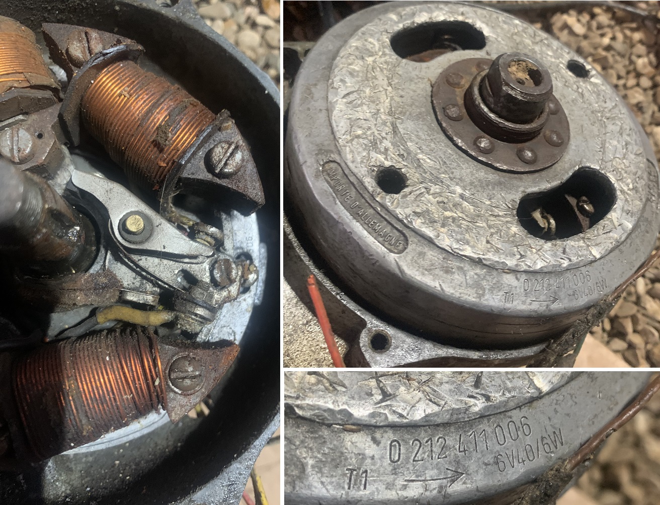
| 243440 | Stator ASsy | o● | ooo | ooo | oooo | ooo | oo | oo | ooo | ooo | ooo | ooo | ooo |
| 243447 | Rotor Assy-NLA | o● | ooo | ooo | oooo | ooo | oo | oo | ooo | ooo | ooo | ooo | ooo |
| 243449 | CDI Unit Assy | o● | ooo | ooo | oooo | ooo | oo | oo | ooo | ooo | ooo | ooo | ooo |
| 243450 | Ignition Coil Assy | o● | ooo | ooo | oooo | ooo | oo | oo | ooo | ooo | ooo | ooo | ooo |
| 243451 | Pug Cap Assy-OB | o● | ooo | ooo | oooo | ooo | oo | oo | ooo | ooo | ooo | ooo | ooo |
| 243455 | MC80 Carburetor | o● | ooo | ooo | oooo | ooo | oo | oo | ooo | ooo | ooo | ooo | ooo |
| 243485 | Gasket | o● | ooo | ooo | oooo | ooo | oo | oo | ooo | ooo | ooo | ooo | ooo |
| 243486 | Gasket | o● | ooo | ooo | oooo | ooo | oo | oo | ooo | ooo | ooo | ooo | ooo |
| 243487 | Upper Triple-OB | o● | ooo | ooo | oooo | ooo | oo | oo | ooo | ooo | ooo | ooo | ooo |
| 243488 | Handlebar Clamp-OB | o● | ooo | ooo | oooo | ooo | oo | oo | ooo | ooo | ooo | ooo | ooo |
| 243489 | Fork Leg RH | o● | ooo | ooo | oooo | ooo | oo | oo | ooo | ooo | ooo | ooo | ooo |
| 243490 | Fork Leg LH | o● | ooo | ooo | oooo | ooo | oo | oo | ooo | ooo | ooo | ooo | ooo |
| 243491 | Rubber Insert Piece 17"-OB | o● | ooo | ooo | oooo | ooo | oo | oo | ooo | ooo | ooo | ooo | ooo |
| 243492 | Tube 2.50x17-OB | o● | ooo | ooo | oooo | ooo | oo | oo | ooo | ooo | ooo | ooo | ooo |
| 243493 | Tire 2, 5-17"-OB | o● | ooo | ooo | oooo | ooo | oo | oo | ooo | ooo | ooo | ooo | ooo |
| 243494 | Rubber Insert Piece 14"-OB | o● | ooo | ooo | oooo | ooo | oo | oo | ooo | ooo | ooo | ooo | ooo |
| 243495 | Tube 3.00 X 14 " | o● | ooo | ooo | oooo | ooo | oo | oo | ooo | ooo | ooo | ooo | ooo |
| 243496 | Tire 3-14" | o● | ooo | ooo | oooo | ooo | oo | oo | ooo | ooo | ooo | ooo | ooo |
| 243604 | Brake pad (each) | oo | ooo | ooo | oooo | ooo | oo | oo | ooo | ooo | ooo | ooo | ooo |
| 243607 | Stop switch 08-on disk brake | oo | ooo | ooo | oooo | ooo | ●● | ●● | o●● | o●● | ooo | ooo | ooo |
| 260216 | Thrust bolt | oo | o●♣ | ●●● | ●●●● | ●●● | ●● | ●● | ●●● | ●●● | ●●● | ●●● | ●●● |
| 260217 | Kickstart spring | oo | o●♣ | ●●● | ●●●● | ●●● | ●● | ●● | ●●● | ●●● | ●●● | ●●● | ●●● |
| 632512 | Front sprocket Arrow 27T | ●o | ooo | ooo | oooo | ooo | oo | oo | ooo | ooo | ooo | ooo | ooo |
| 700334 | Magneto flywheel puller | ●o | ooo | ooo | oooo | ooo | oo | oo | ooo | ooo | ooo | ooo | ooo |
| 702856 | Dis-assembly crankshaft bearin | ●o | ooo | ooo | oooo | ooo | oo | oo | ooo | ooo | ooo | ooo | ooo |
| 706485 | Extractor | ●o | ooo | ooo | oooo | ooo | oo | oo | ooo | ooo | ooo | ooo | ooo |
| 708253 | Dis-assembly condor bush d10 | ●o | ooo | ooo | oooo | ooo | oo | oo | ooo | ooo | ooo | ooo | ooo |
| 710807 | Propeller gears backlash | ●o | ooo | ooo | oooo | ooo | oo | oo | ooo | ooo | ooo | ooo | ooo |
| 712024 | Starter device spring holder | ●o | ooo | ooo | oooo | ooo | oo | oo | ooo | ooo | ooo | ooo | ooo |
| 712025 | Starter device spring holder | ●o | ooo | ooo | oooo | ooo | oo | oo | ooo | ooo | ooo | ooo | ooo |
| 714011 | Engine repair stand | ●o | ooo | ooo | oooo | ooo | oo | oo | ooo | ooo | ooo | ooo | ooo |
| 716714 | Dis-assbly condor bush d12 | ●o | ooo | ooo | oooo | ooo | oo | oo | ooo | ooo | ooo | ooo | ooo |
| 730159 | Clutch drum holder | ●o | ooo | ooo | oooo | ooo | oo | oo | ooo | ooo | ooo | ooo | ooo |
| 731155 | Crankshaft bearings puller | ●o | ooo | ooo | oooo | ooo | oo | oo | ooo | ooo | ooo | ooo | ooo |
| 731183 | Chain sprocket holder | ●o | ooo | ooo | oooo | ooo | oo | oo | ooo | ooo | ooo | ooo | ooo |
| 732152 | Stern bracket rivetting tool | ●o | ooo | ooo | oooo | ooo | oo | oo | ooo | ooo | ooo | ooo | ooo |
| 732193 | Dial gauge support | ●o | ooo | ooo | oooo | ooo | oo | oo | ooo | ooo | ooo | ooo | ooo |
| 732202 | Flywheel holder | ●o | ooo | ooo | oooo | ooo | oo | oo | ooo | ooo | ooo | ooo | ooo |
| 732367 | Mainshaft needle bearings | ●o | ooo | ooo | oooo | ooo | oo | oo | ooo | ooo | ooo | ooo | ooo |
| 735753 | Crankshaft mounting fork | ●o | ooo | ooo | oooo | ooo | oo | oo | ooo | ooo | ooo | ooo | ooo |
| 735888 | Dis-assembly of crankshaft | ●o | ooo | ooo | oooo | ooo | oo | oo | ooo | ooo | ooo | ooo | ooo |
| 736913 | Brake shoes spring installing | ●o | ooo | ooo | oooo | ooo | oo | oo | ooo | ooo | ooo | ooo | ooo |
| 737080 | Oil pump centering pin | ●o | ooo | ooo | oooo | ooo | oo | oo | ooo | ooo | ooo | ooo | ooo |
| 737535 | Clutch spring setting tool | ●o | ooo | ooo | oooo | ooo | oo | oo | ooo | ooo | ooo | ooo | ooo |
| 737536 | Roller clutch installer | ●o | ooo | ooo | oooo | ooo | oo | oo | ooo | ooo | ooo | ooo | ooo |
| 737784 | Clutch disk's setting tool | ●o | ooo | ooo | oooo | ooo | oo | oo | ooo | ooo | ooo | ooo | ooo |
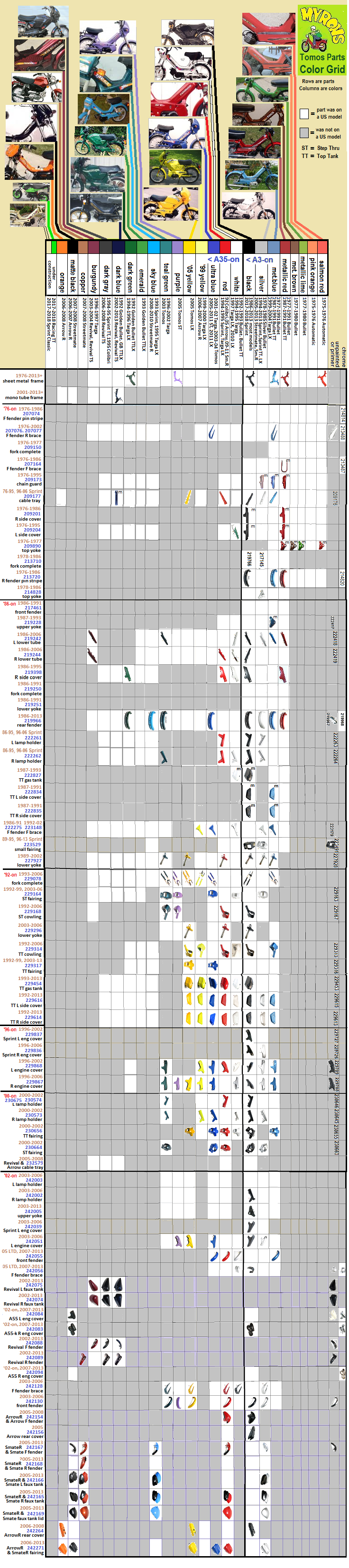
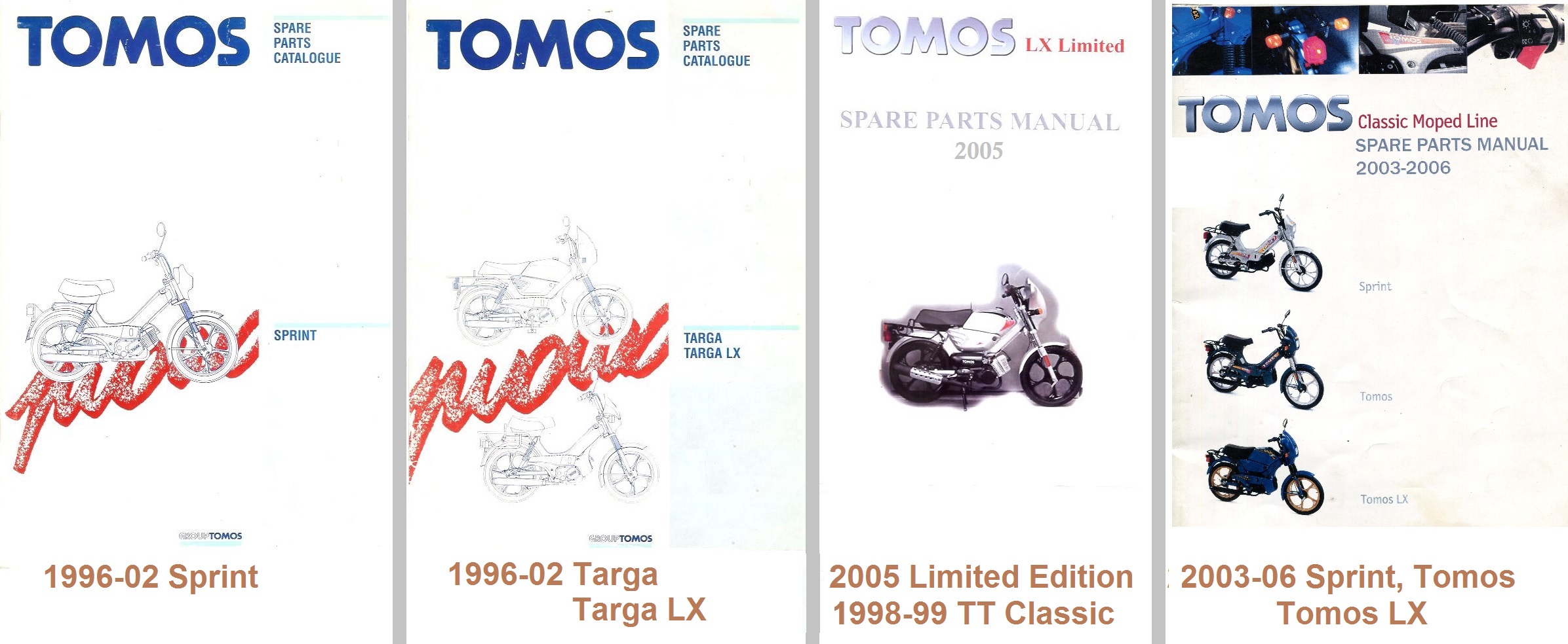
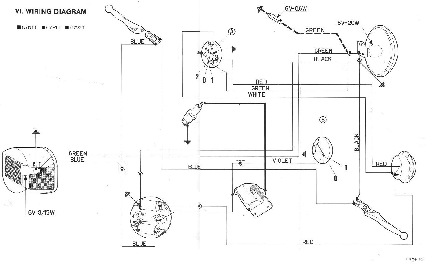
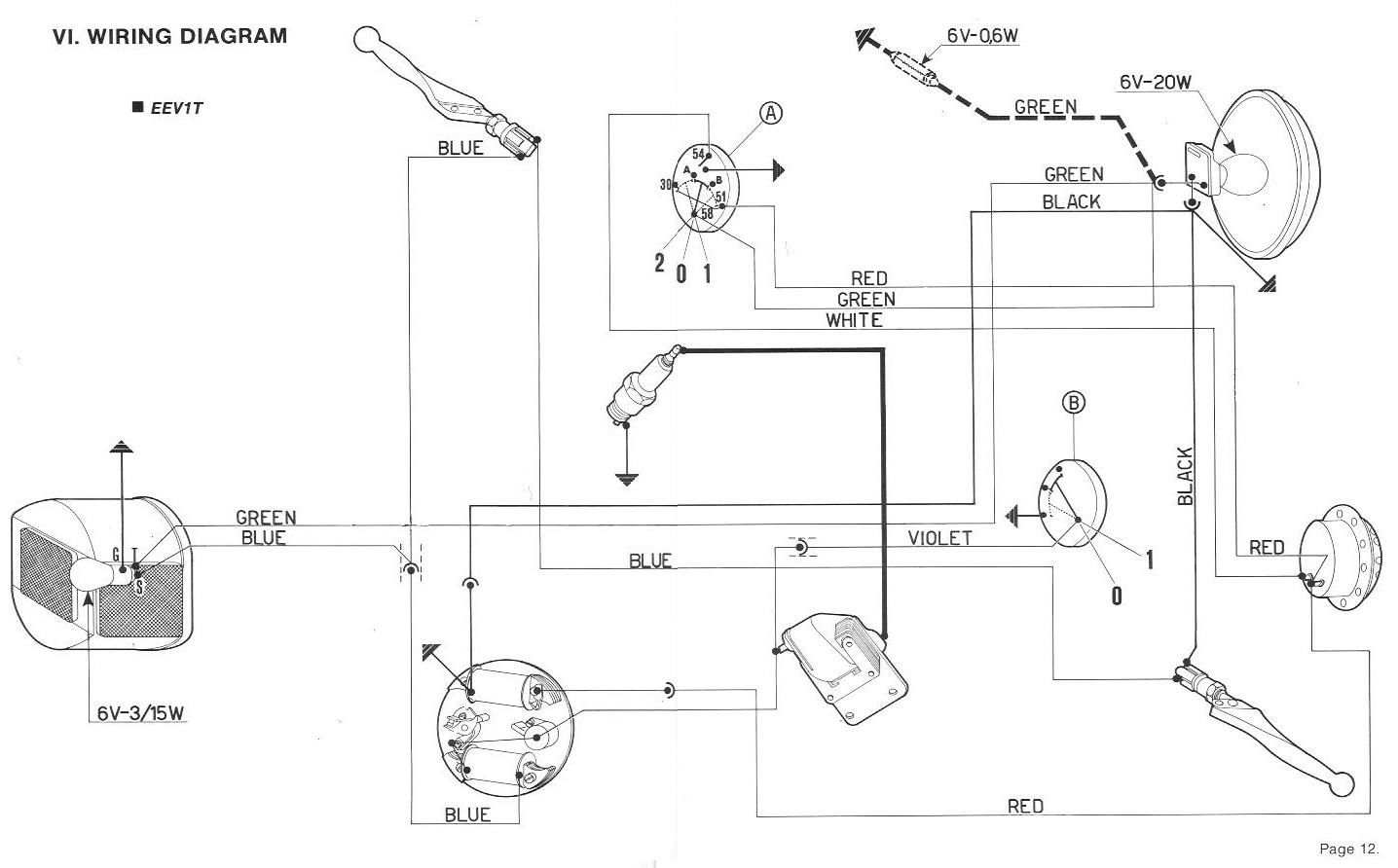
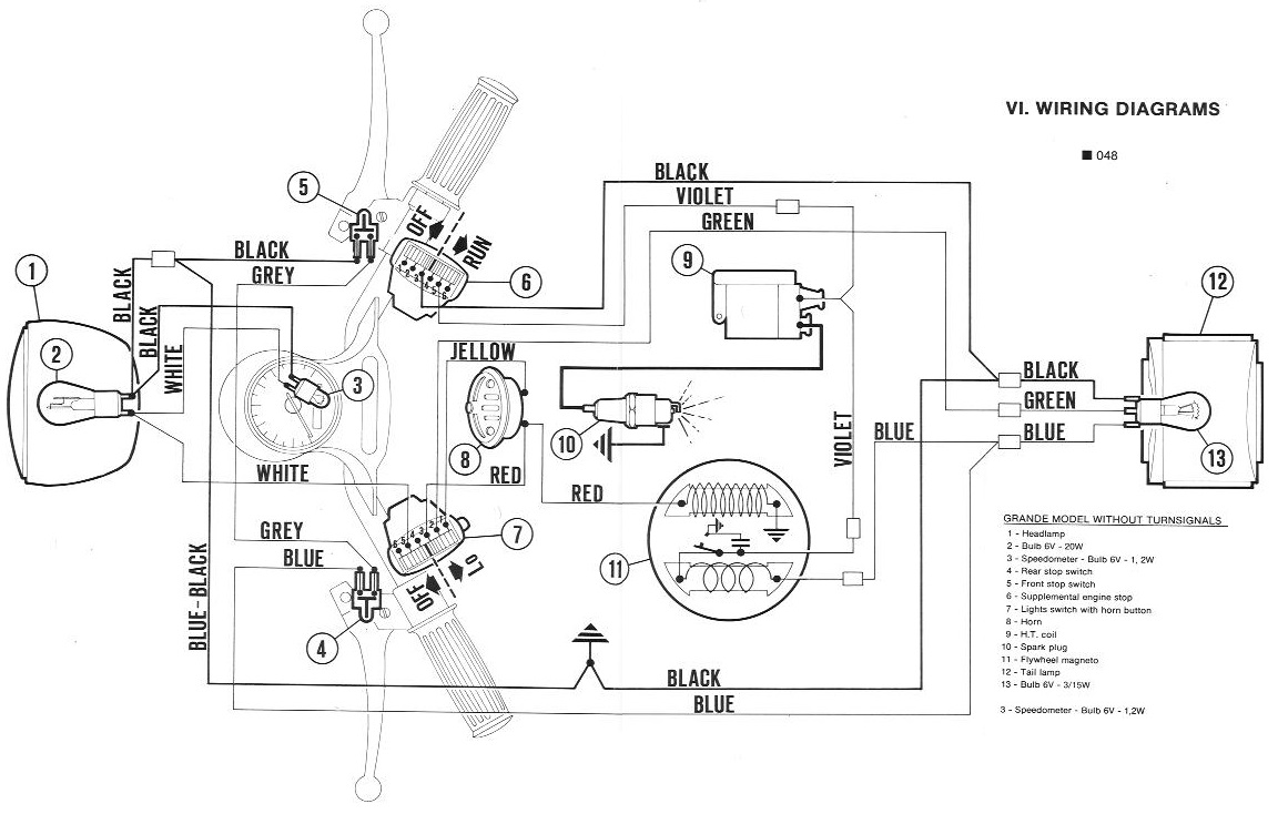
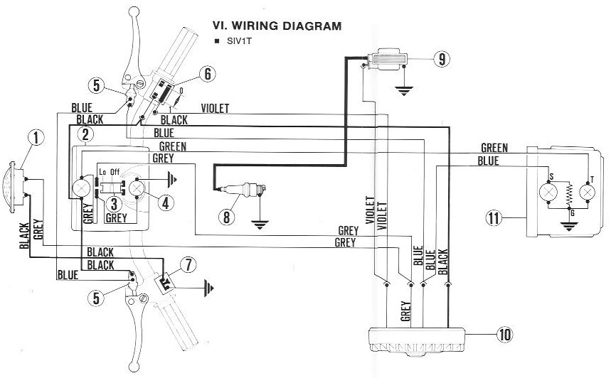
2. Grid Columns
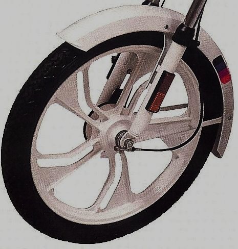
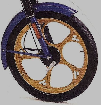
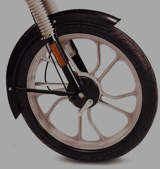
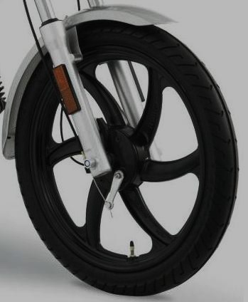
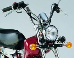
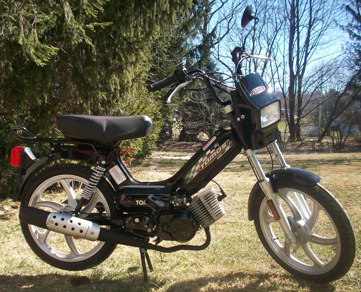
Each grid column is a parts manual covering one or more models. Here are the 34 grid columns, and the parts manual or groups they represent. Only the covers are shown.
1 2

1: Accessories and Tools
2: 2005-06 MC80 (3-sp)
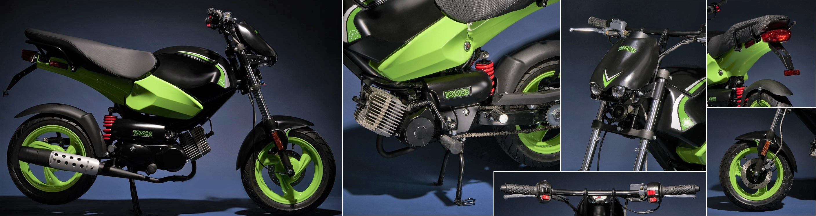
This is the miscellaneous category. Here is anything that was not original equipment. Manuals, tools, optional equipment, and promotional materials, are in this category.
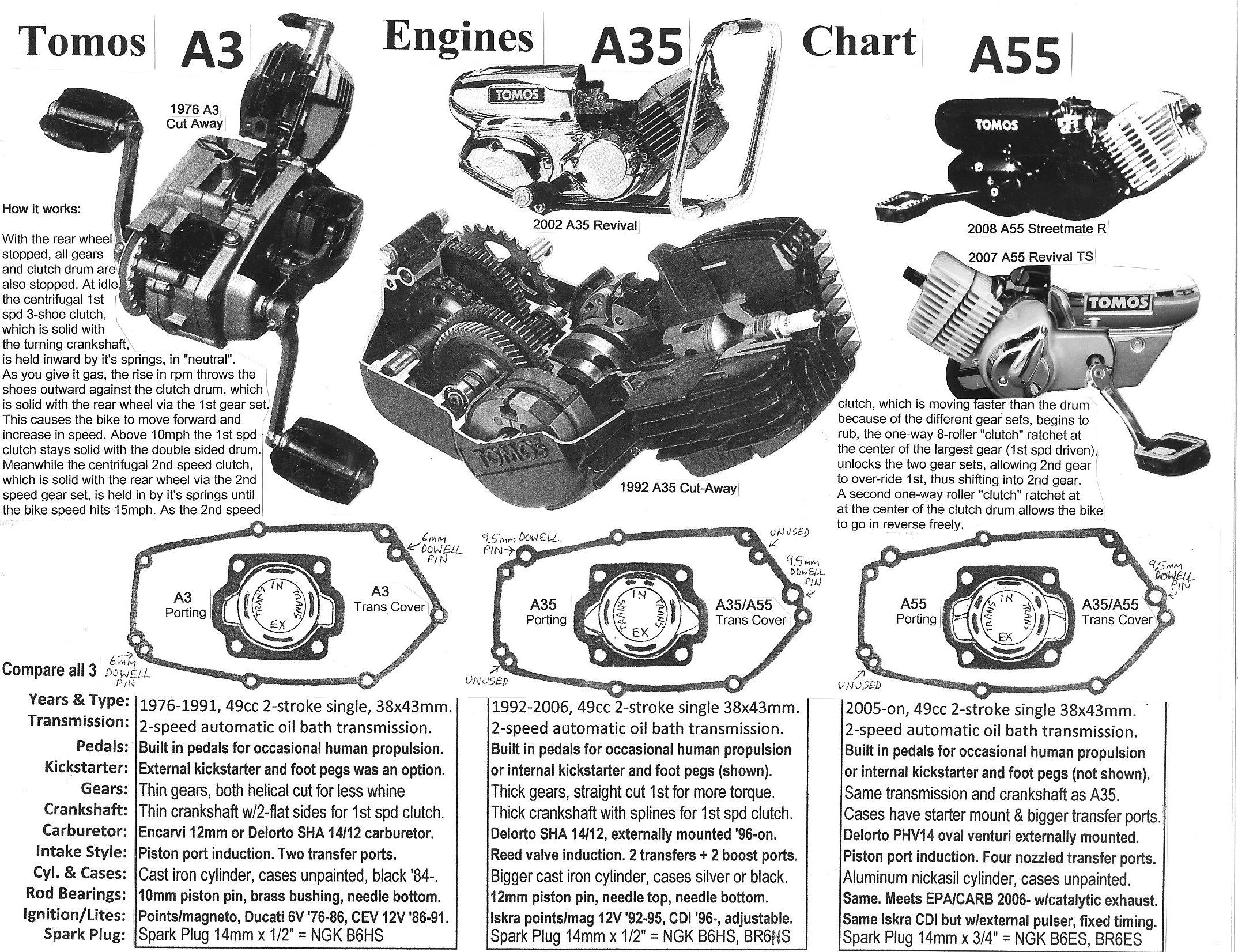
The Tomos MC80 is a completely different engine, not an A35. So it is all alone here. Most of the non-engine parts are also different from MC50.
VIN codes: VIN digits 5 and 6 encode the model. This is for on-road vehicles worldwide, since 1981. Here VIN codes are purple. Note that machines made before 1981 do not have a 17-digit VIN with codes. They just have a serial number.
Speed versions: SP is 30mph, GM is 25 mph, SL is 20mph
30405
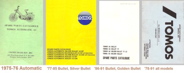
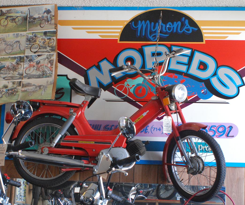
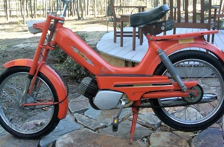
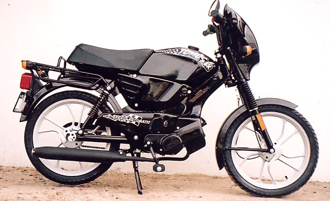
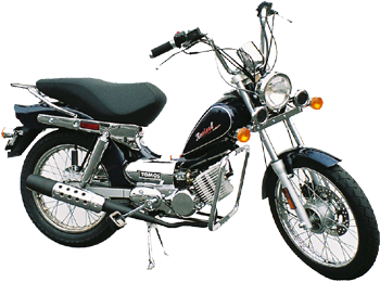
3: 1975-76 A3 Automatic spare parts manual
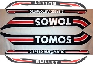
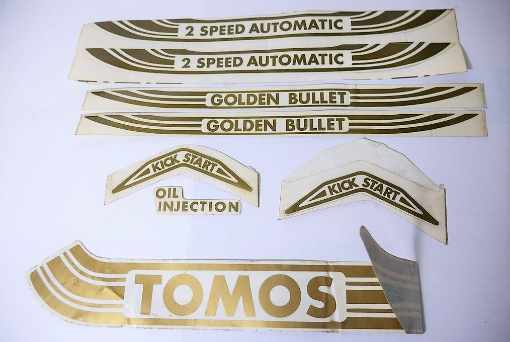
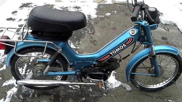
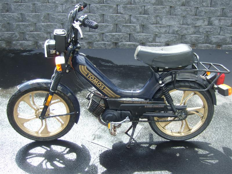
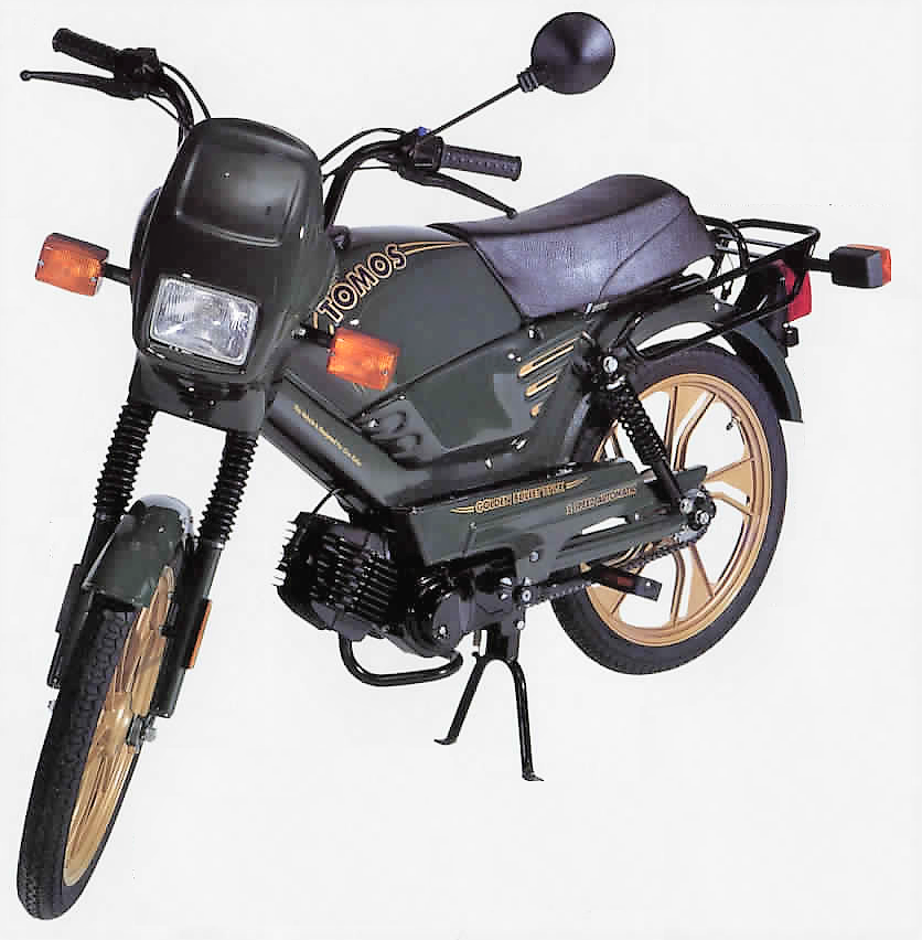
4: 1976-86 A3 Bullet, Silver Bullet, Golden Bullet
5: 1986-91 A3 Bullet, Golden Bullet xxxxxxxx
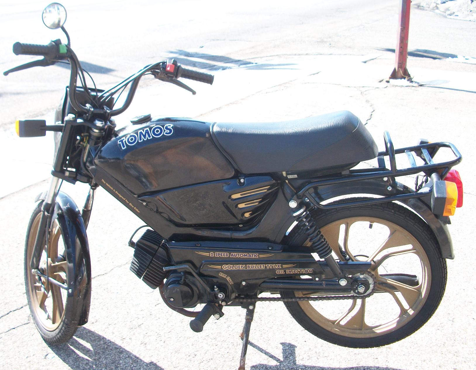
5: 1986-91 A3 Bullet TT, Golden Bullet TTLX
4 and 5: 1978-91 Tomos A3 “all models”
3: 1975-76 Automatic SP orange, salmon
4: 1976-79 Bullet mred,mblue,brown,lime
3: pedal pedal pedal kick
4:1980-85 Bullet
.SP(01) GM(02) SL(03) metred, metblue
1978-81 Silver Bullet
..SP(04) GM(05) SL(06) silver
’81-83 Sil Bullet SP(07) silver spoke wheel
1981-85 Silver Bullet
.SP(08) GM(09) SL(10) silver
‘1985 Golden Bullet SP(11) black
5: 1986-91 Bullet SP(12) met red, met blue
5: Golden Bullet SP(13) black
5: 1986 Bullet TT SP(14) (??) mred, mblue
5: Golden TTLX SP(19) (??) black
5:1986-89 A3-01 GM(20) metallic blue
60708
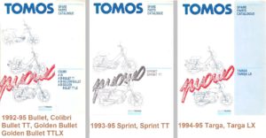
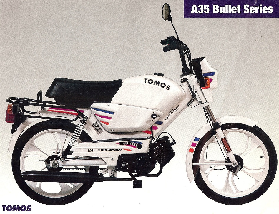
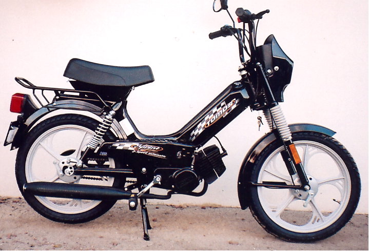
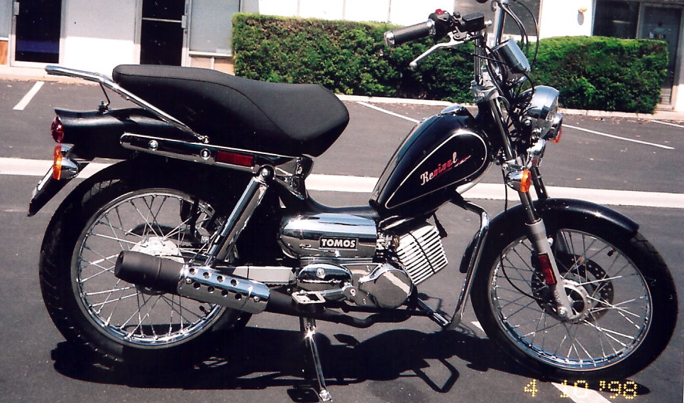
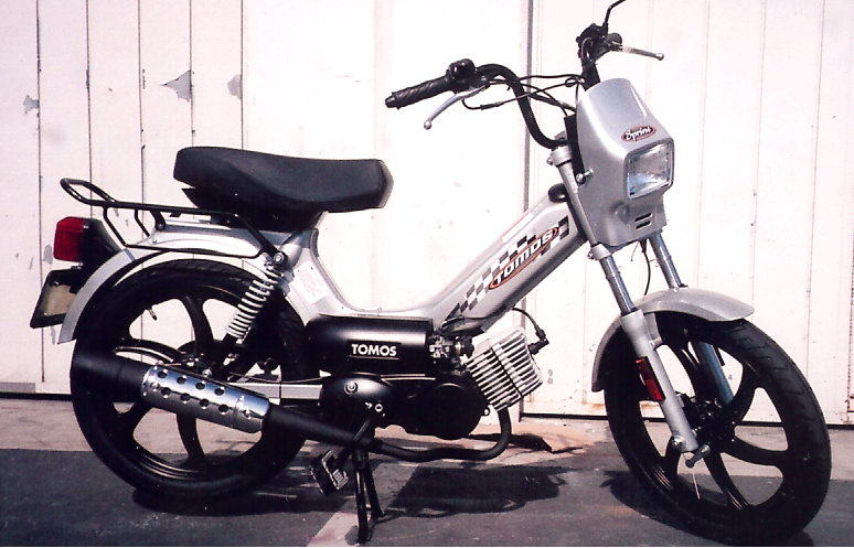
6: 1992-93 A35 Bullet, Colibri, Golden Bullet, TT
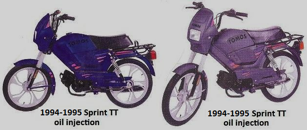
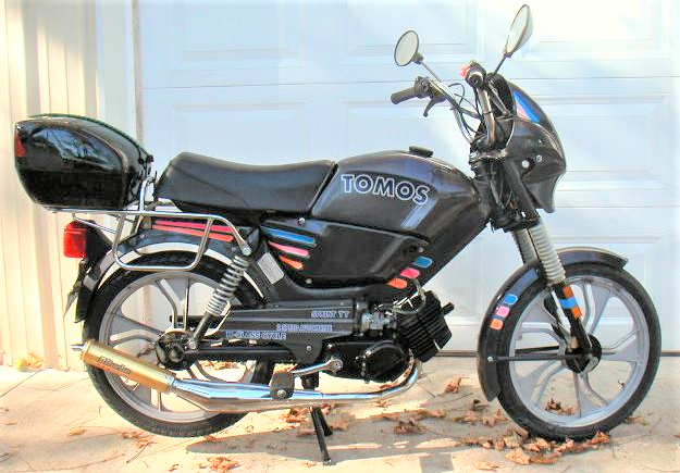
7: 1993-95 A35 Sprint, Sprint TT parts manual
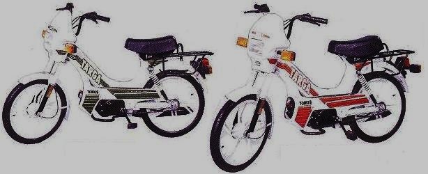
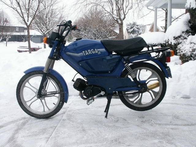
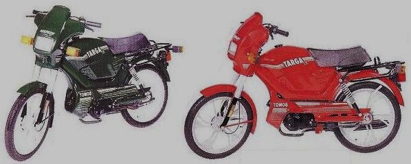
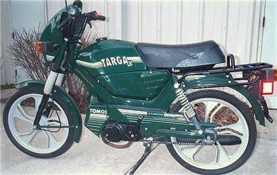
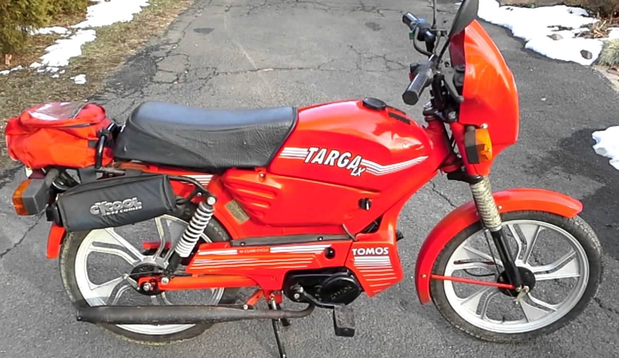
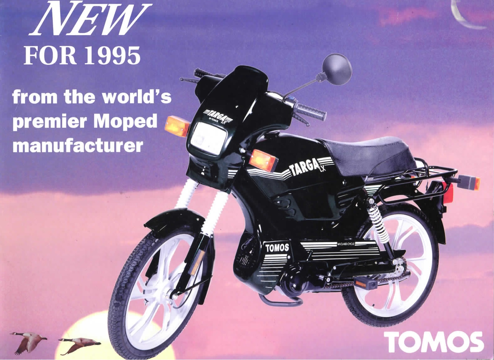
8: 1994-95 A35 Targa, Targa LX parts manual
After 1991 all speed versions were SP (30mph)
6: 1992-94 Bulle pedal kick
6: 1992-93 Bullet (34) (40) white
6: 1992-Bullet TT (35) (40) white
6: 1 Golden Bullet (38) (40) dk blue, dk grn, black
1992 Gold B. TTLX (39) (41) dark blue, dark green
1993 Gold B. TTLX (39) (41) black, emerald
6: 1992-95 Colibri (36) (37) red, dark gray
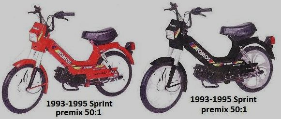
7: 1993-95 Sprint (42) (43) red, black, sky blue
7: 19 Sprint oil inj (42) (58) silver
7 Sprint TT oil inj (56) (58) silver, blue, dark gray
8: 1994-95 Targa (44) (47) white/green
8: 1994-95 Targa (45) (49) white/red
8: 1994 Targa LX (46) (48) black, red, dk grn

9 10 11 12

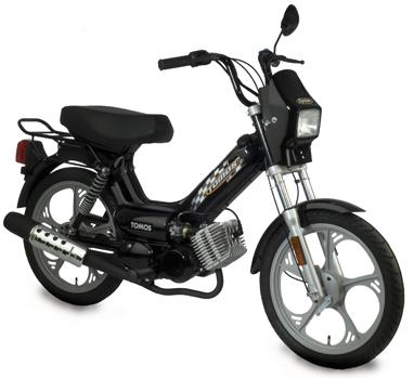
9: 1996-02 A35 Targa, Targa LX parts manual
10: 1996-02 A35 Sprint spare parts manual
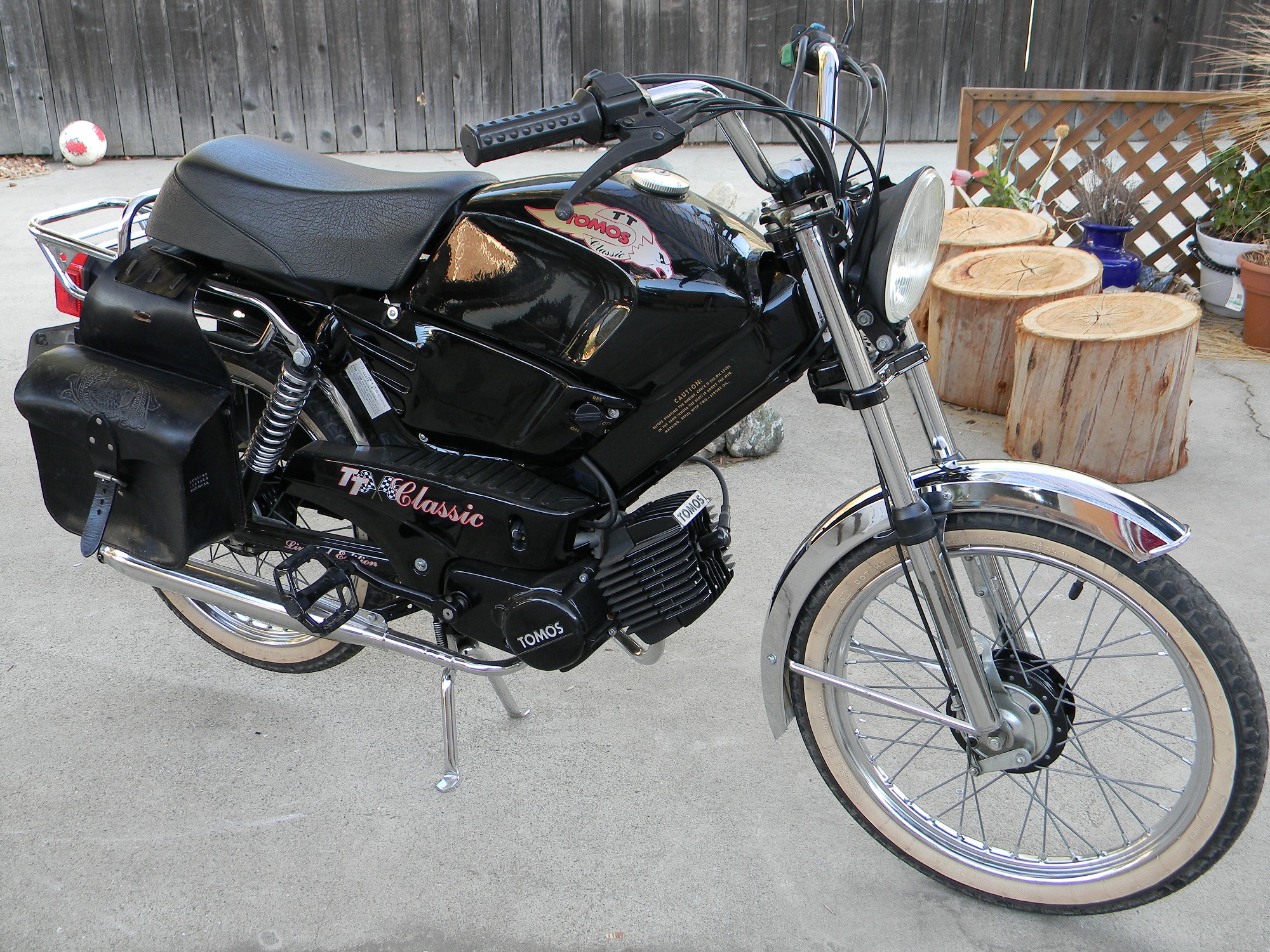
11: 2005 A35 Limited Ed. or 1998 TT Classic
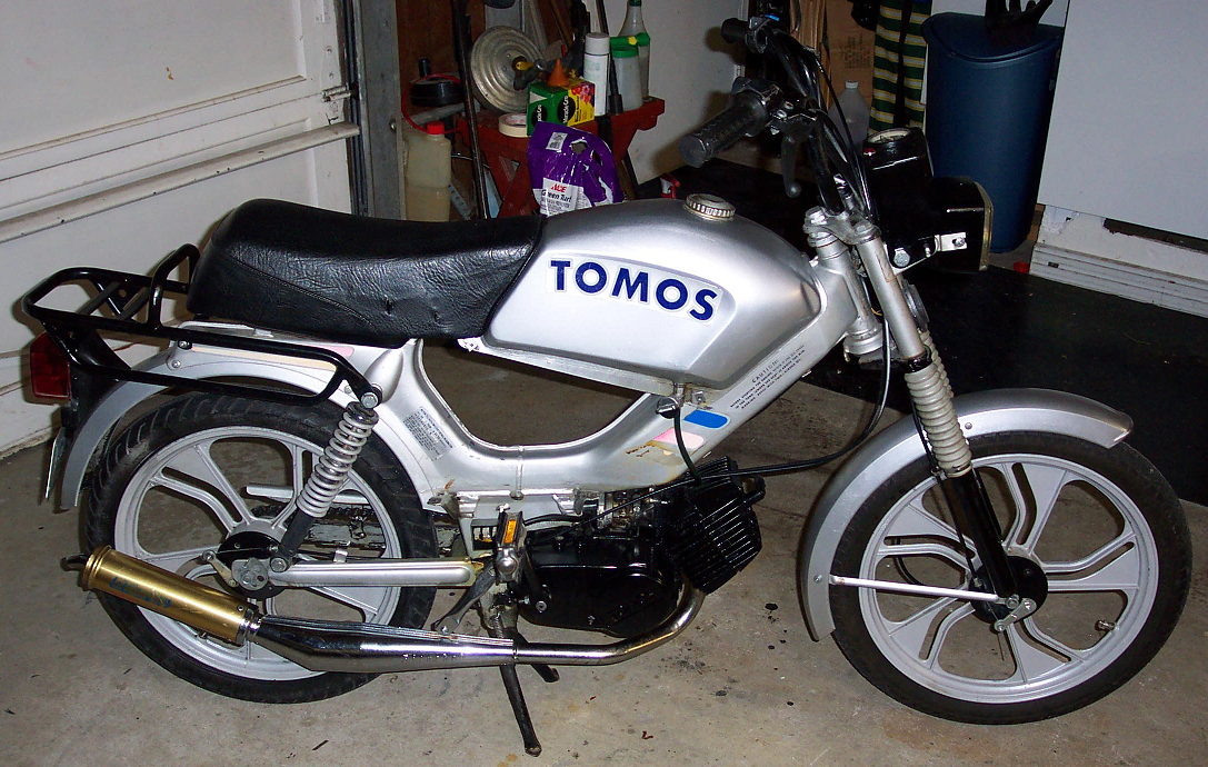
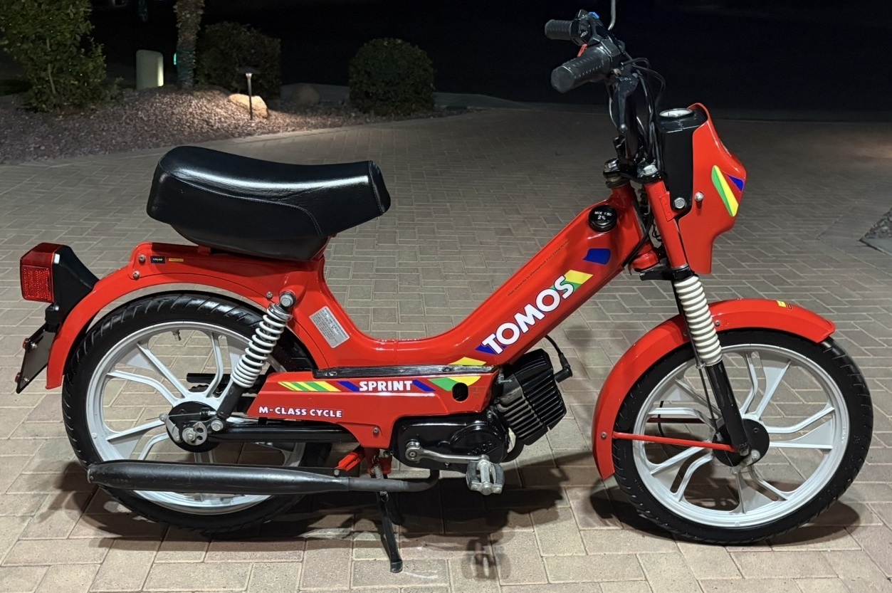
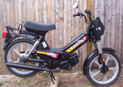
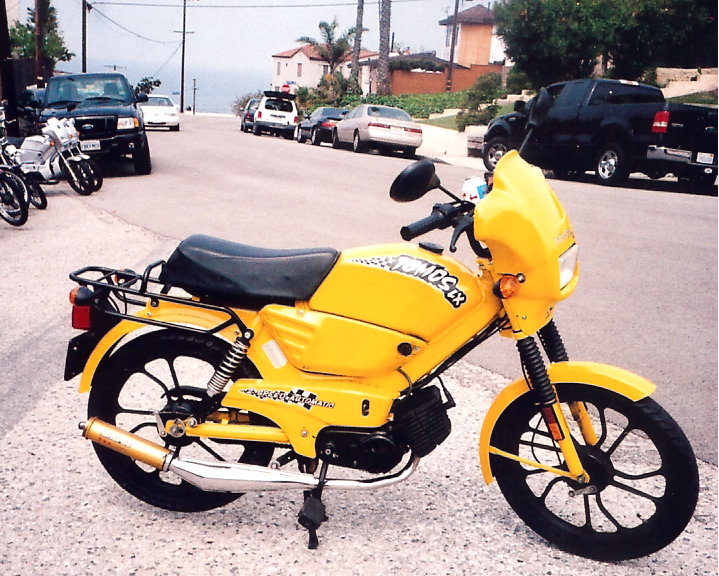
12: 2003-06 A35 Sprint, Tomos, Tomos LX
After 1995 the carburetor was side mount.
09: 1996-02 Targa xx pedal kick
09: 1996-02 Targa xx (63) (66) burgundy, teal
09: 1996-02 Targa LX (62) (65) black,red,mblu
09: 1996-02 Targa LX (62) (65) 99yellow,white
10: 1996-02 Sprint Xx (61) (64) silver, black
11: 1998-99 TT Classic (69) (??) black
11: 2005-05 LX Limited (62) (65) silver
12: 2003-06 Sprint xXx (61) (64) black
12: 2003-06 Tomos/ST (63) (66) blk,ublu,red,pur
12: 2003-06 Tomos LX (62) (65) black, metblu
12: 2003-06 Tomos LX (62) (65) red, 05yellow
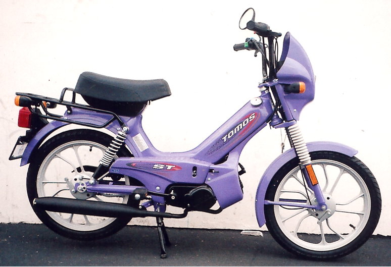
In 2005 the “Tomos” (formerly Targa) became ST.
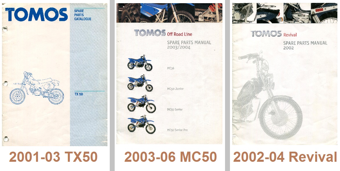
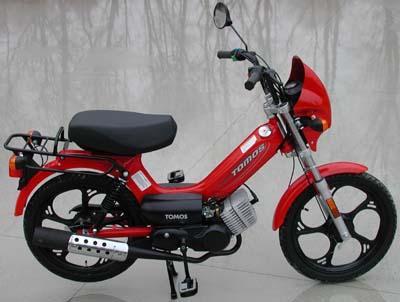
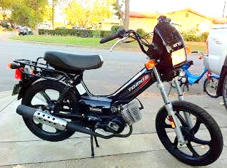
13 14 15
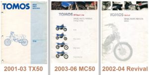
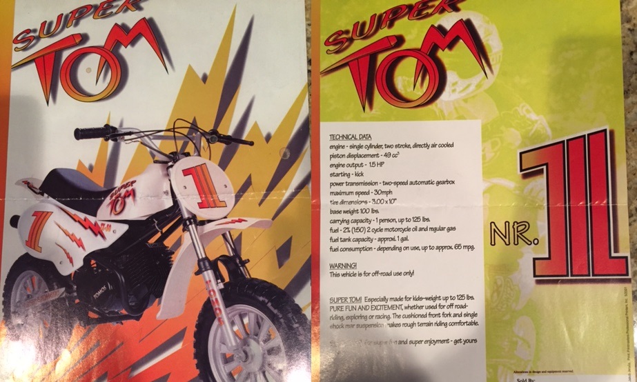
13: 2001-03 A35 TX50 Super Tom manual
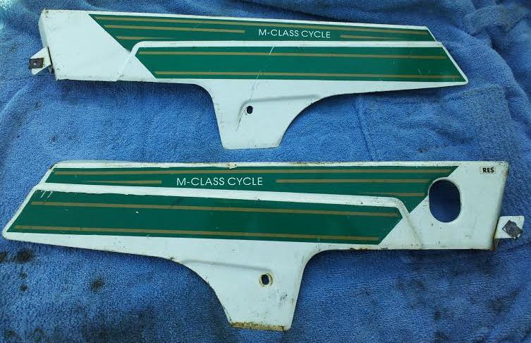
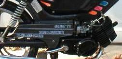
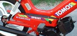
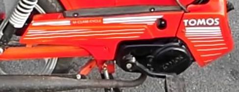
14: 2003-06 A35 MC36, MC50 Jr, Sr, Sr Pro
15: 2002-04 A35 Revival spare parts manual
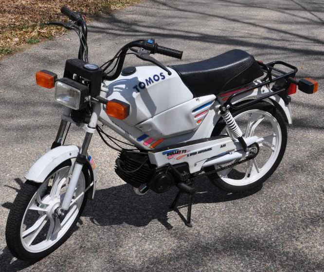
13: 2001-03 TX50 Super Tom white
14: 2003-06 MC36, MC50 Jr, Sr, Sr Pro blue
15: 2002-04 Revival dark blue A=kick, B=pedal
15: 2002-04 Revival burgundy A=kick, B=pedal
A35 Revival (kick) is VIN code 75, (pedal) is 72.
16 17

16: 2005 A55 Arrow spare parts manual
17: 2006-08 A55 Arrow R parts manual
16: 2005-05 Arrow silver and black A=kick, B=pedal
16: 2005-05 Arrow silver and red A=kick, B=pedal
17: 2006-08 Arrow R black, red A=kick, B=pedal
17 matte black, orange, 99 yellow A=kick, B=pedal
Arrow (kick) is VIN code ??, (pedal) is 78.
Arrow R (kick) is VIN code 76, (pedal) is 77.
18 19

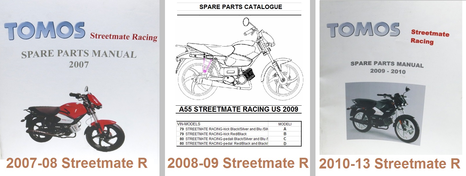
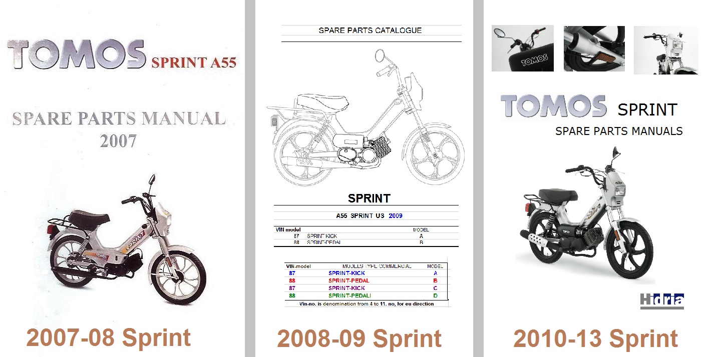
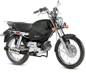
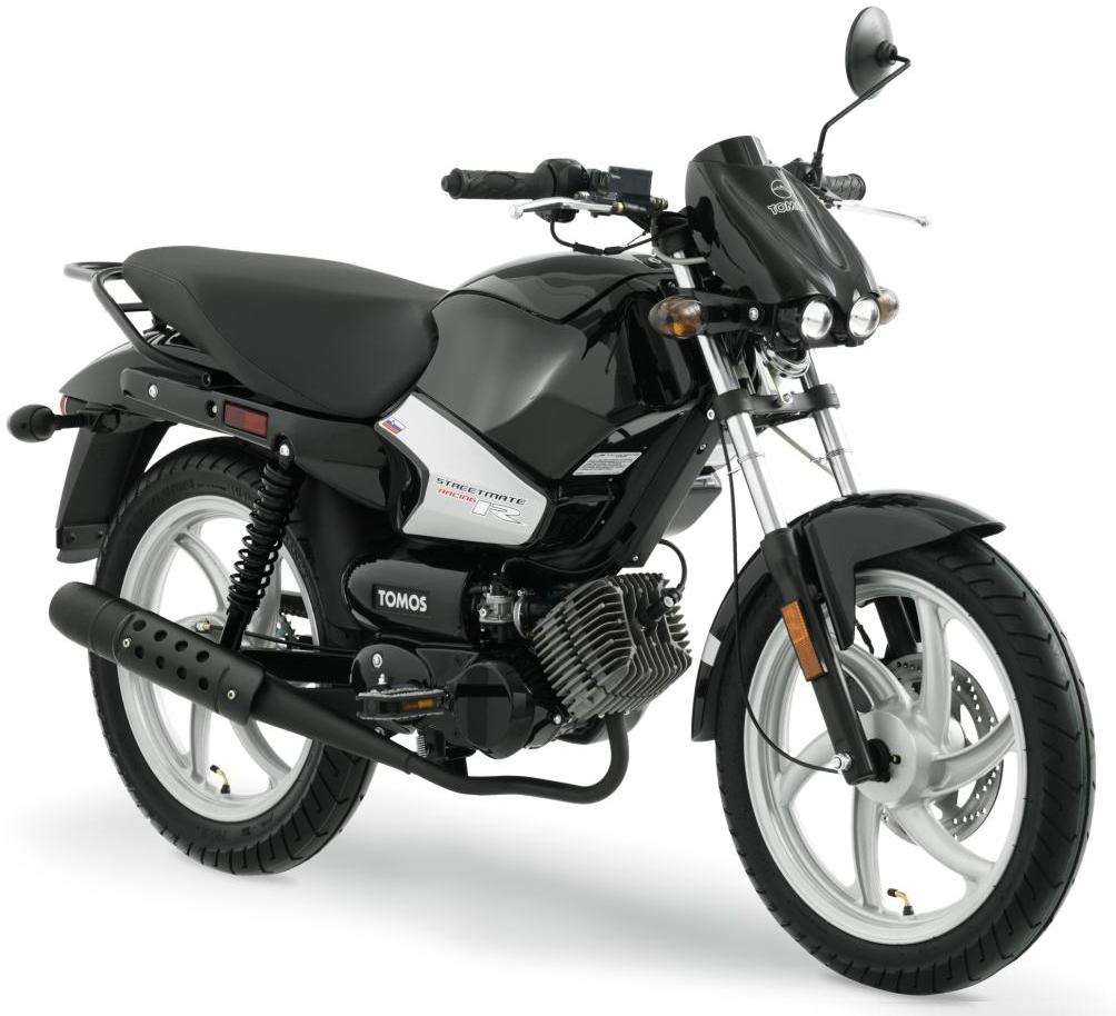
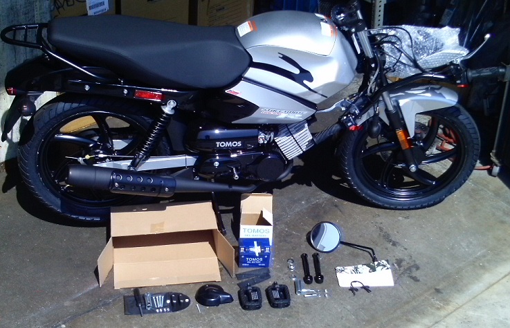
18: 2008-09 Streetmate R parts catalog (paper)
18: 2008-09 Streetmate R parts catalog (Excel)
19: 2010-13 Streetmate R parts catalog (PDF)
18: 2008-09 Streetmate R red B=kick, D=pedal
18: 2008-09 a sky blue, black A=kick, C=pedal
18: 2008-09 a lite blue, black D=pedal only
19: 2010-13 Streetmate R sblu A=kick, C=pedal
18: 2008-09 a bl red, silver B=kick, D=pedal
A & C have silver wheels, B & D have black wheels.
’08-08 A & B (kick) VIN code 80, C & D (pedal) 79.
’09-13 A & B (kick) VIN code 93, C & D (pedal) 94.
20 21 22

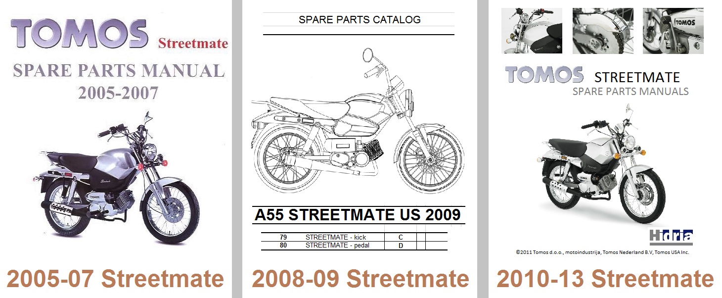
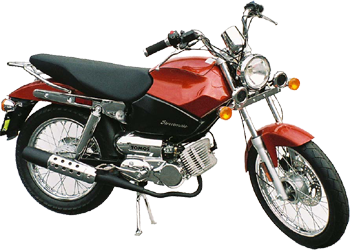
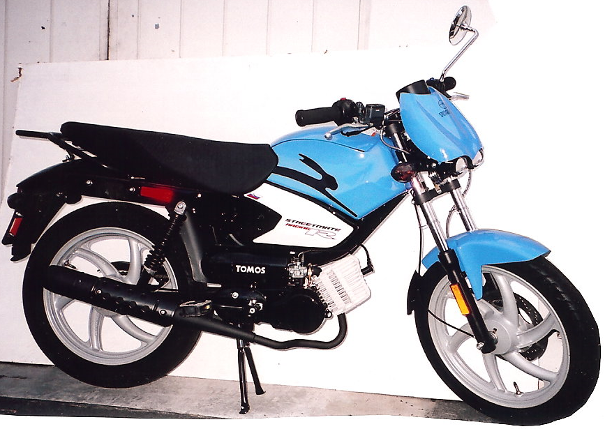
20: 2005-07 Streetmate parts catalog (paper)
21: 2008-09 Streetmate parts catalog (Excel)
22: 2010-13 Streetmate parts catalog (PDF)
20: 2005-07 Streetmate silver A=kick, B=pedal
23: 20S copper, matte black A=kick, B=pedal
21: 2008-09 Streetmate silver A=kick, B=pedal
21
22: 2010-13 Streetmate silver A=kick, B=pedal
A55 Streetmate (kick) VIN code 80, (pedal) is 79.
23 24 25

23: 2004-07 A55 Revival TS parts catalog (paper)
24: 2008-09 A55 Revival TS parts catalog (Excel)
25: 2010-13 A55 Revival TS parts catalog (PDF)
23: 2004-07 Revival TS dark blue A=kick,B=pedal
23: 2004-07 Revival TS burgundy A=kick,B=pedal
23: 2004-07 Revival TS dark gray A=kick,B=pedal
24: 2008-09 Revival TS dark blue A=kick,B=pedal
23: 2004-07 Revival TS dark gray A=kick,B=pedal
25: 2010-13 Revival TS dark blue A=kick,B=pedal
A55 Revival TS (kick) is VIN code 81, (pedal) is 82.
26 27 28

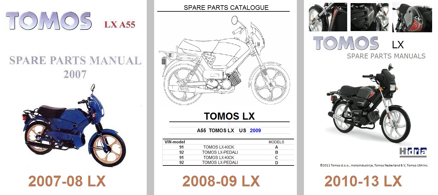
26: 2007-08 A55 LX, a ’02-04 (A35) is shown.
27: 2008-09 A55 LX, 07-to-early-08 is shown.
28: late-08 & 09 LX also had the 2010 wheels.
26: 2007-08 LX black A=kick, B=pedal
30: silver, red C=kick, D=pedal
27: 2008-09 LX black A=kick, B=pedal
27: 2008-09 LX red C=kick, D=pedal
28: 2010-13 LX black A=kick, B=pedal
30: silver, ultra blue C=kick, D=pedal
A & B had shiny black eng. covers, silver wheels.
C & D had matte black eng. covers, black wheels.
The 2007 LX catalog was the last paper version.
2008-11 was Excel, 2011-13 was PDF.
A and C are VIN code 91, B and D are 92.

29 30 31

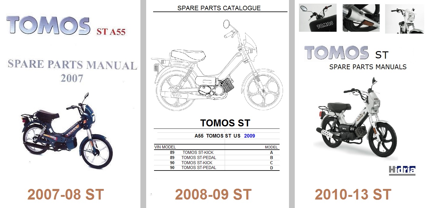
29: 2007-08 A55 ST, a 2002-04 (A35) is shown.
30: 2008-09 A55 ST, a 07-to-early-08 is shown.
31: 2010-13 A55 ST, a 2008-13 Sprint is shown.
29: 2007-08 ST black A=kick, B=pedal
30: red, ultra blue C=kick, D=pedal
30: 2008-09 ST black A=kick, B=pedal
30: red, ultra blue C=kick, D=pedal
31: 2010-13 ST black A=kick, B=pedal
30: red, ultra blue C=kick, D=pedal
A & B had shiny black eng. covers, silver wheels.
C & D had matte black eng. covers, black wheels.
The 2007 ST catalog was the last paper version.
2008-11 was Excel, 2011-13 was PDF.
A and C are VIN code 89, B and D are 90.
32 33 34

32: 2007-08 Sprint, a 2002-05 (A35) is shown.
33: 2008-09 Sprint, a ’07-to-early-08 is shown.
34: late-2008 & 09 Sprint had the 2010 wheels.
32: 2007-08 Sprint black A=kick, B=pedal
33: 2008-09 Sprint black A=kick, B=pedal
33: 2008-09 Sprint silver C=kick, D=pedal
34: 2010-13 Sprint black A=kick, B=pedal
34: 2010-13 Sprint silver C=kick, D=pedal
A & B had shiny black eng. covers, silver wheels.
C & D had matte black eng. covers, black wheels.
2007 Sprint catalog was the last paper version.
2008-11 was Excel, 2011-13 was PDF.
A and C are VIN code 87, B and D are 88.
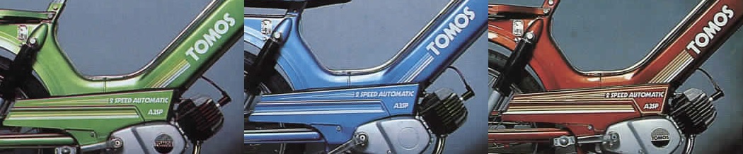
3. Bike Colors (US models)
1975 A3 Automatic pink orange, salmon red
1976 A3 Automatic pink orange, salmon red
1977 A3 Bullet lime,brown,met red, met blue
1978 A3 Bullet lime,brown,met red, met blue Silver Bullet,silver
1979 A3 Bullet lime,brown,met red, met blue Silver Bullet,silver
1980 A3 Bullet, Bullet TT met red, met blue Silver Bullet,silver
1981 A3 Bullet, Bullet TT met red, met blue Silver Bullet,silver
1982 A3 Bullet, Bullet TT met red, met blue Silver Bullet,silver
1983 A3 Bullet, Bullet TT met red, met blue Silver Bullet,silver
1984 A3 Bullet, Bullet TT met red, met blue Silver Bullet,silver
1985 A3 Bullet, Bullet TT met red, met blue Silver Bullet,silver
1986 A3 Bullet, Bullet TT met red, met blue Golden Bullet (early) black
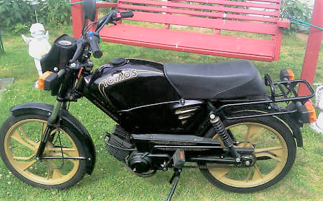
1986 A3 Bullet, Bullet TT met red, met blue Golden Bullet, black
1987 A3 Bullet, Bullet TT met red, met blue Golden Bullet, Golden Bullet TTLX black
1988 A3 Bullet, Bullet TT met red, met blue Golden Bullet, Golden Bullet TTLX black
1989 A3 Bullet, Bullet TT met red, met blue Golden Bullet, Golden Bullet TTLX black
1990 A3 Bullet, Bullet TT met red, met blue Golden Bullet, Golden Bullet TTLX black
1991 A3 Bullet, Bullet TT met red, met blue Golden Bullet, Golden Bullet TTLX black
1992 A35 Bullet whitex Golden Bullet dark blue Bullet TT white Golden Bullet TTLX dark blue, dark green
1993 A35 Sprint red, sky blue Gold.Bullet black Bullet TT white Golden Bullet TTLX black, emerald
1994 A35 Sprint red, black Targa wht/red,wht/grn Sprint TT silver,blu,dk gray Targa LX red, dark green
1995 A35 Sprint red, black Targa wht/red,wht/grn Sprint TT silver, dark gray Targa LX black,red,dk grn,sky blue
1996 A35 Sprint silver, black Targa black, teal, silver, burgundy Targa LX black, red, white, hunter(dark) green
1997 A35 Sprint silver, black Targa black, teal, silver, burgundy Targa LX black, red, white
1998 A35 Sprint silver, black Targa black, teal, silver, burgundy Targa LX black, red, metallic blue
1999 A35 Sprint silver, black Targa black, teal, silver, xxxx xxx Targa LX black, red, met blue, 99 yellow
2000 A35 Sprint silver, black Targa black, teal, silver, xxxx xxx Targa LX black, red, met blue, 99 yellow
2001 A35 Sprint silver, black Targa black, teal, silver, ultra blue Targa LX black, red, metallic blue
2002 A35 Sprint silver, black Targa black, teal, silver, ultra blue Targa LX black, red, metallic blue
2002 A35 Revival xx dark blue
2003 A35 Sprint silver, black Tomos black, teal, silver,ultra blue Tomos LX black, red, metallic blue
2003 A35 Revival xx dark blue, burgundy
2004 A35 Sprint silver, black Tomos black, xxx red, xxultra blue Tomos LX black, red, metallic blue
2004 A35 Revival xx dark blue, burgundy
2004 A55 Revival TS dark blue, burgundy
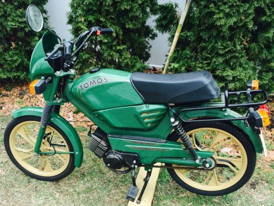
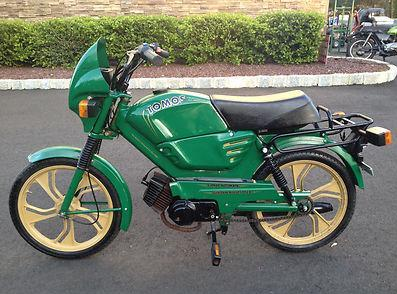
2005 A35 Sprint silver, black xxx ST black, xxx red, xxultra blue, purple LX black, red, 05 yellow
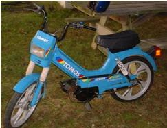
2005 A55 Revival TS dark blue, burgundy Streetmate silver xxxxx xxxxxx LX Limited Edition silver
2005 A55 Arrow silver/red, silver/black
2006 A35 Sprint silver, black xxx ST black, xxx red, xxultra blue xxxxx LX black, red
2006 A55 Revival TS dark blue, dark gray Streetmate silver
2006 A55 Arrow R matte black, orange, 99 yellow
2007 A55 Sprint silver, black xxx ST black, xxx red, xxultra blue xxxxx LX black, red, silver
2007 A55 Revival TS dark blue, dark gray Streetmate silver, copper, matte black
2007 A55 Arrow R matte black, orange, 99 yellow
2008 A55 Sprint silver, black xxx ST black, xxx red, xxultra blue xxxxx LX black, red, silver
2008 A55 Revival TS dk blue, dk gray Streetmate silver, copper, black Streetmate R black, red, sky blue
2008 A55 Arrow R black (gloss), orange, red
2009 A55 Sprint silver, black xxx ST black, xxx red,xx ultra blue xxxxx LX black, silver
2009 A55 Revival TS dark blue Streetmate silver, copper, matte black Streetmate R black, red, sky blue
2010 A55 Sprint silver, black xxx ST black, xxx red, xxultra blue xxxxx LX black, silver, white
2010 A55 Revival TS dark blue Streetmate silver, copper, matte black Streetmate R black,red, sky blue
2011 A55 Sprint silver, black xxx ST black, xxx red,xx ultra blue xxxxx LX black, silver, ultra blue
2118 A55 Revival TS dark blue Streetmate silver, copper, matte black Streetmate R silver, red
2012 A55 Sprint silver, black xxx ST black, xxx red xx LX black, silver Streetmate R silver
2013 A55 Sprint silver, black xxx ST black, xxx red xx LX black, silver Streetmate R silver
2014 no US models
2015 no US models
2016 no US models
2017 A55 Sprint (alum. wheels) black Sprint Classic (spoke whls) ivory Racing TT green
2018 A55 Sprint (alum. wheels) black Sprint Classic (spoke whls) ivory Racing TT green
4. Parts Colors
Tomos provided painted parts in different colors, but the parts manuals never mentioned the colors. Some parts manuals say “(state color)”. Some say “painted”. Sometimes “painted” meant always the same color, usually black, and sometimes it meant different colors.
Painted replacement parts were offered in finish coated (laquered or “lakiran” suffix LAK) or primer coated (primered or “grundiran” suffix GRU) versions. Some parts manuals list the primer coated part numbers only.
This color chart supplements all 34 of the Tomos parts manuals, for US models 1976-2013. The list above is the color of every Tomos bike, while the chart below is the color of every Tomos part (than was painted different colors).
Each of the rows is a part. Each part (row) has a application range. For example, part 219242 is “1986 to 2006”. That part can be painted in several different colors.
Each of the columns is a color. Each color (column) has a application range. For example, color met red is “1977 to 1991”.
The application range of a particular colored part is the intersection of the row and column year ranges. So a met red 219242 would be on bikes made from 1986 to 1991.
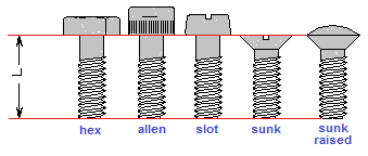
 M5 hex zinc
 M5 phil pan (DIN)
 M5 slot-phil pan (JIS)
 M5 allen button ISO 7380
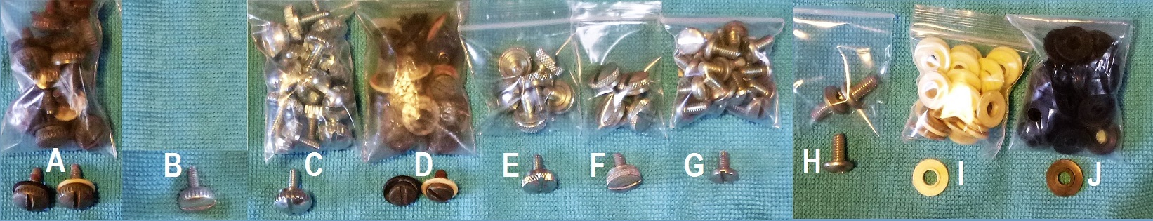
 M6 hex flange
 M6 hex small-flange
 M6 hex8 flange (Honda)
 M6 slot wide raised
 M6 slot truss
 M6 slot sunk
 M6 slot sunk raised
 M6 phil pan JIS
 M6 phil wide (Motobecane)
 M6 phil sunk
 M6 phil sunk raised
 M6 allen (socket)


