Welcome. The wiring diagrams below come from 1) original owners manuals, 2) service manuals, 3) supplement sheets, 4) parts manuals, 5) actual mopeds, wirings, or parts, new or used, or most often 6) a combination of most of those. The manuals and sheets were in the wall of printed material from Myrons Mopeds buyouts of over 20 other moped shops. The raw originals were designed for black and white printing and copying, so they had the wire color names written in text. Myrons Mopeds has colorized them, and eliminated the color names, making them much easier to understand and follow. When needed, they have also been rearranged, scaled, and edited for clarity.
A=====================
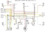
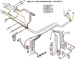
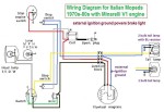
AMF Wiring: This wiring info is for the AMF Roadmaster models 110, 115, 120, 125 with McCullough rear friction drive engine, not the models 140, 141 with Minarelli V1 mid-engine and chain drive.
AMF CDI Ignition Upgrade
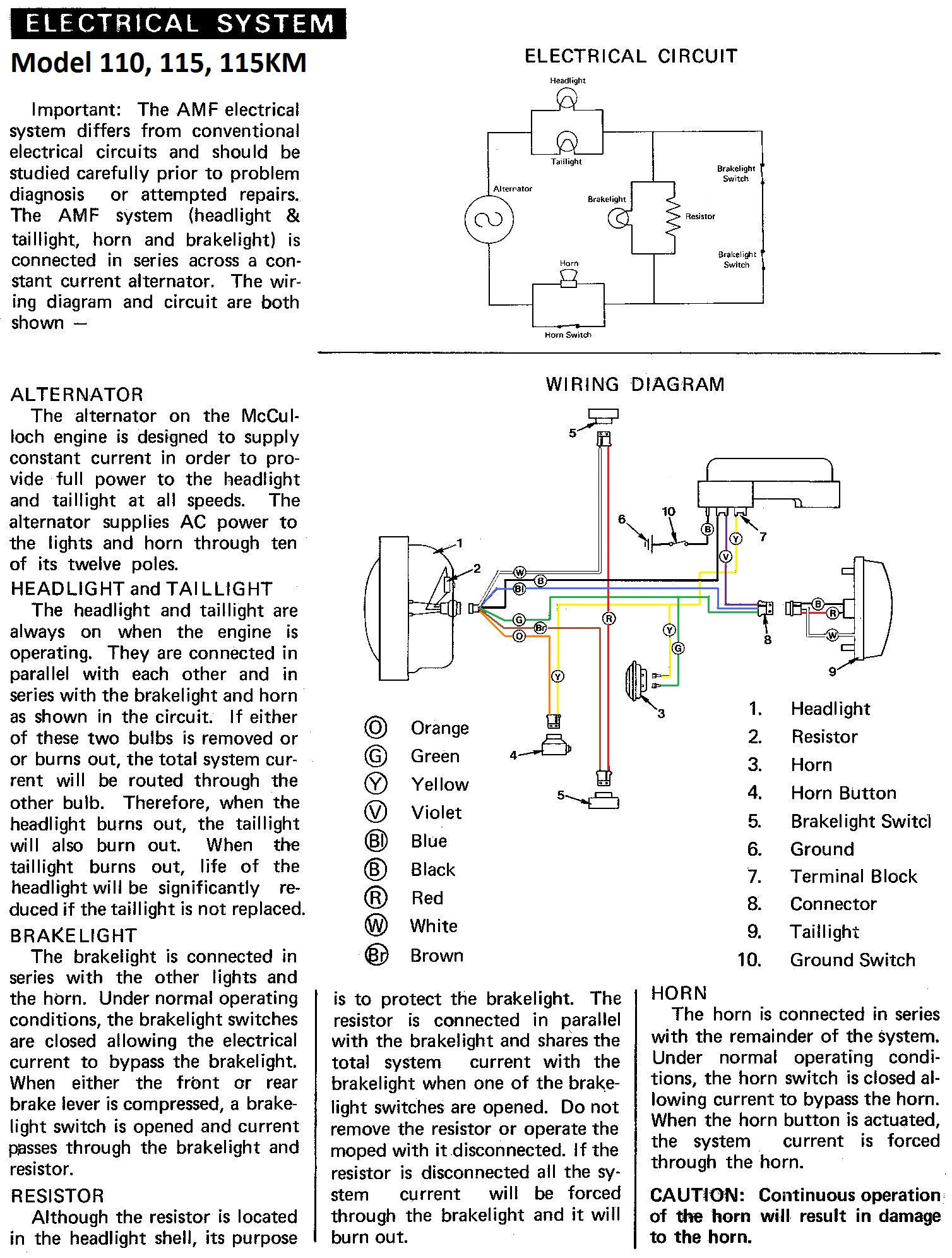
AMF 110,115,115KM
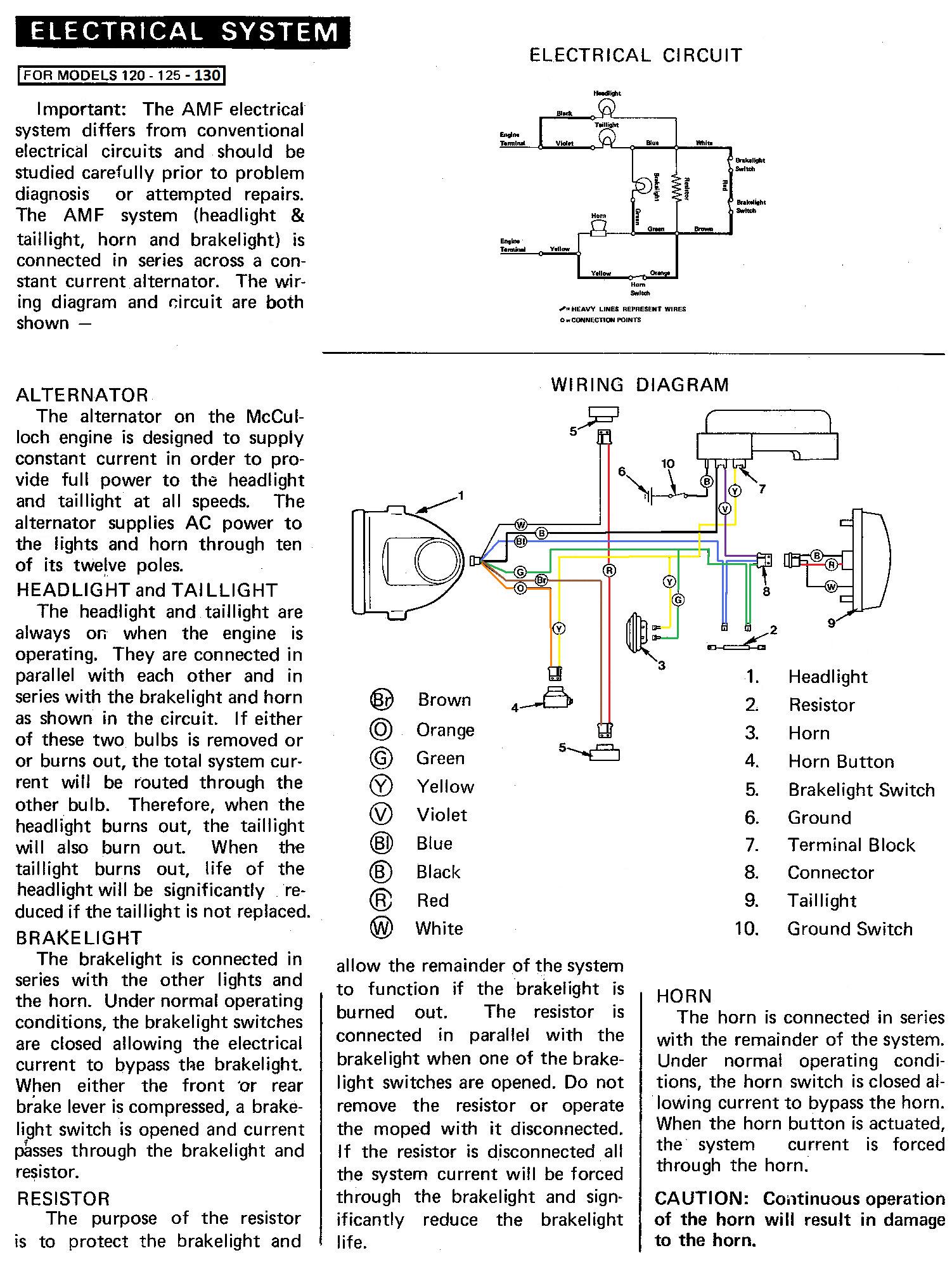
AMF 120, 125, 130

AMF 110 wiring
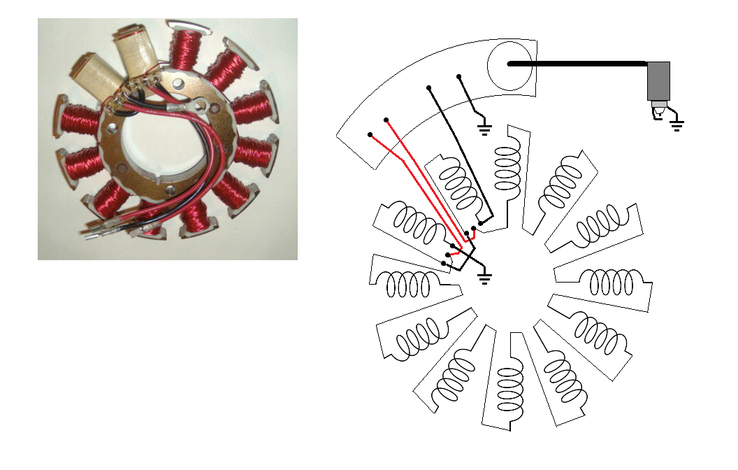
AMS motor, Sachs 505/1D
3-wire Taigene Magneto
90mm Bosch compatible
blue, blue/black, yellow
Honda points & puller tool
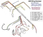
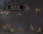
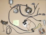
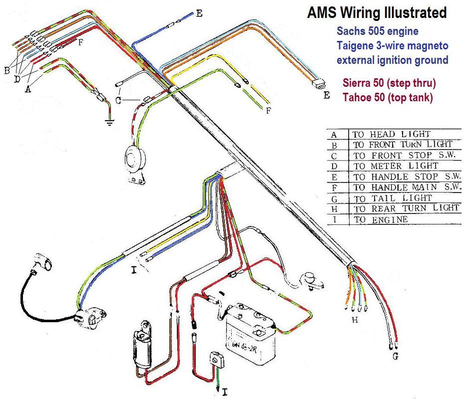
AMS Wiring Illustrated
Sachs 505/1D engine
Taigene 3-wire magneto
external ignition ground
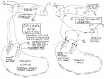
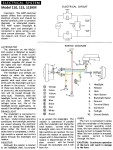
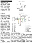
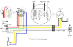
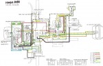
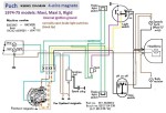
AMS Wiring: AMS Sierra 50 (step thru), Tahoe G1 (top tank) and Tahoe G2 (top tank 2 speed manual) have the same wiring as General 5 Star ST, except with a Taigene magneto, 3-wire with external ignition ground blue/black for battery charging, no ignition switch in the fork lock, and possibly minor differences in some connectors and grounds. Always ground the blue/black if there is no spark.
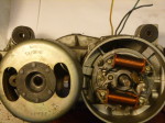
The Taigene FP43 90mm 3-wire magneto is Bosch-compatible. Too bad it was prone to loose spark, even with the blue/black wire grounded and the points functioning. Some needed upgraded to an actual Bosch magneto.
AMS & Angel Battery Versions: Angel/Speed Birds use a 6N2-2A small 6 volt battery, AMS uses a 6N4B-2A. Modern replacement batteries have different wires than the original ones did. See section “B” Battery Wires.
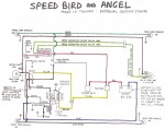
Angel Wiring 1) and 2)
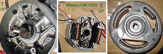
Wtemco or Bosch 3-wire
external ignition ground
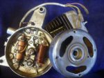
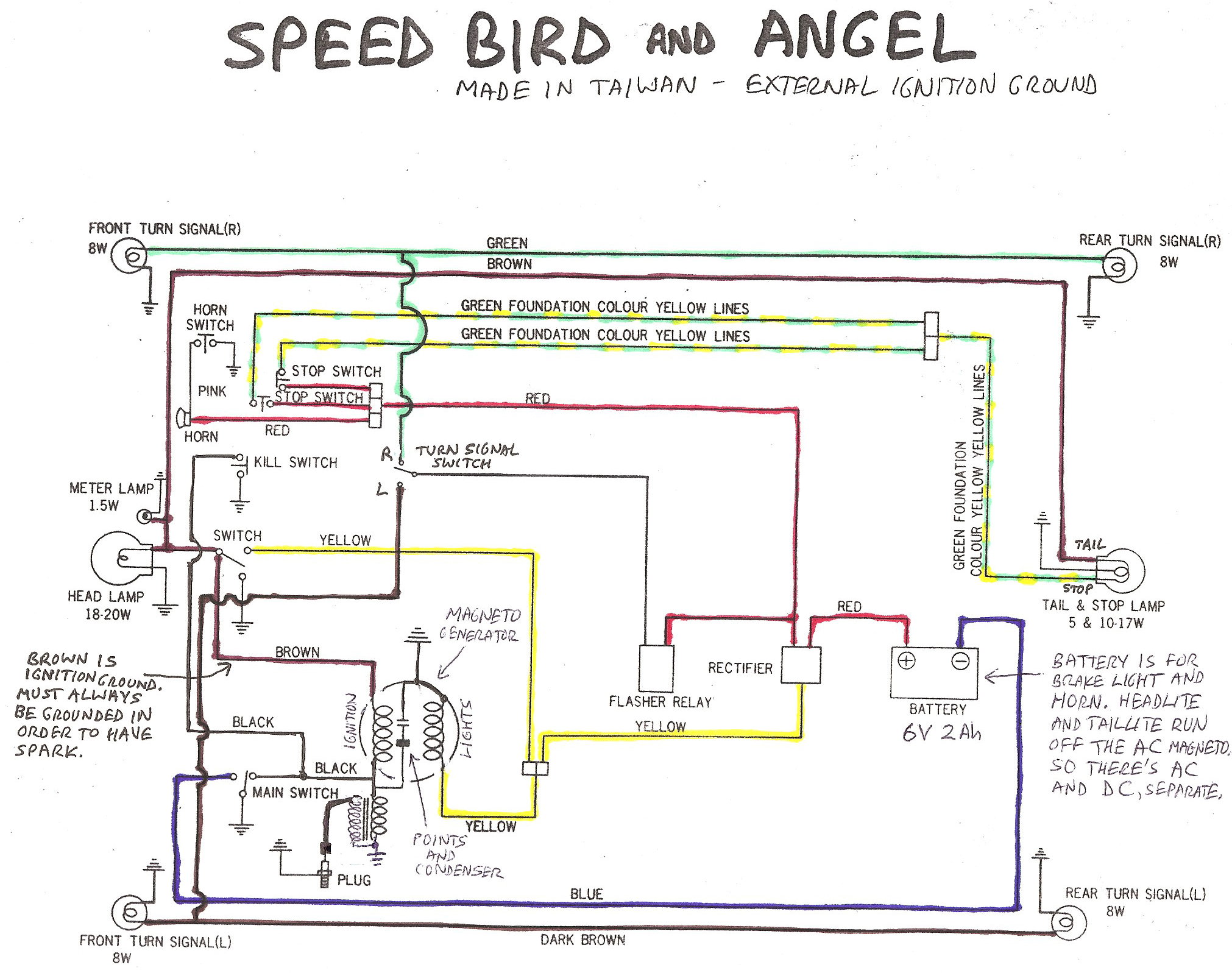
Angel: 1970’s Angel and Speed Bird mopeds, made in Taiwan by TYM, can have three different magnetos and two different wirings. These all have Ø90-three-M4-screw stator plates, and Ø90 (90mm ID) flywheel-rotors.
1) Bosch 0212-112-053, with brown (external ignition ground), yellow, black wires. The brown wire is the “tail” of the ignition source coil, and must always go to ground to have spark. It helps to power the headlight. So the headlight or headlight wires can cause the ignition to loose spark.
2) Wtemco FHA ?????, with brown (external ignition ground), yellow, black wires. This whole magneto interchanges with Bosch 0212-112-053, but the internal coils are different. The flywheel, stator plate, points, condenser, the wire colors and wire plugs are all the same.
3) Wtemco FHA 11035, (internal ignition ground) with red, yellow, and black wires. This is the same as the other Wtemco magneto, except for the source coils (armatures). The headlight wiring is different from the others, in that the yellow does not get help from the ignition ground. This would make the headlight dimmer, but at the same time there is a separate output for battery charging, so the headlight gets brighter from that. The net effect is slightly dimmer.
1) Bosch 0212-112-053
external ignition ground
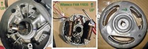
3) Wtemco FHA-11035, internal ignition ground
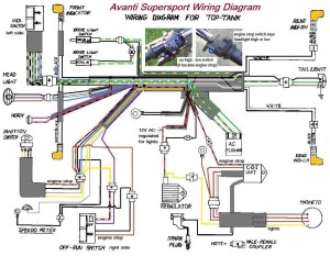
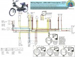
Avanti Supersport (top tank) Wiring
Seel 4-wire CDI magneto
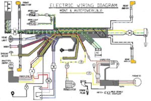
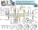
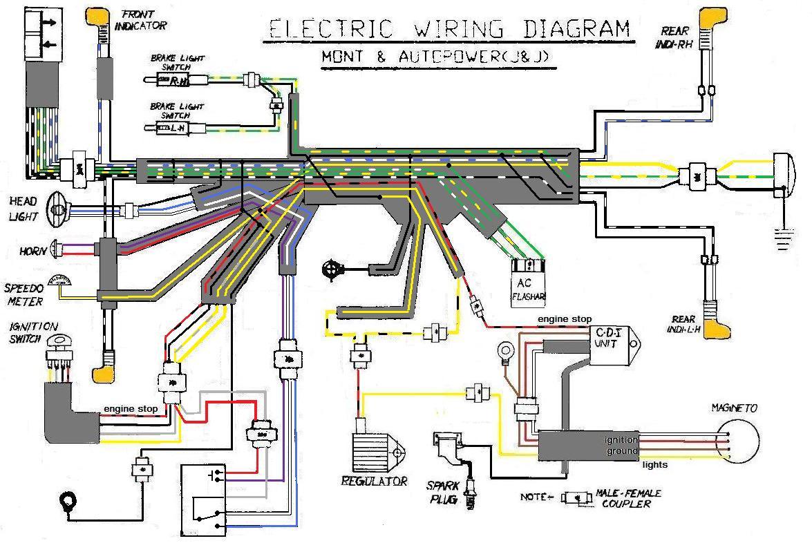
Avanti Autopower and Avanti Mont Wiring
Garelli-clone engine, Seel 4-wire CDI magneto
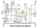
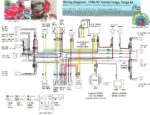
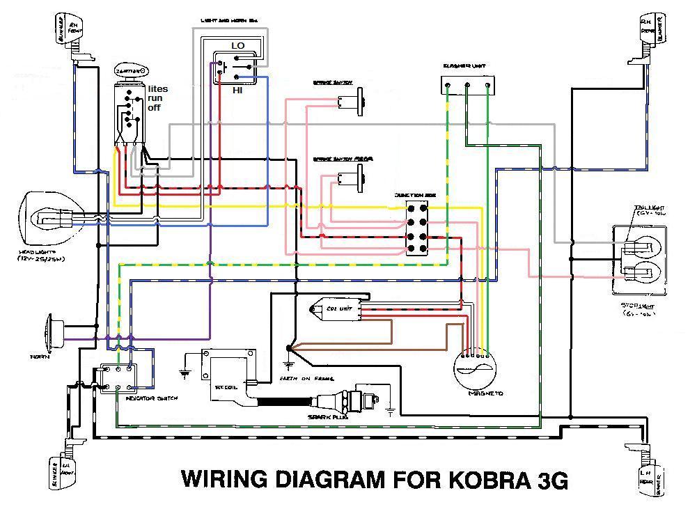
Avanti Kobra 3G
Garelli 2-speed clone
Seel 6-wire CDI magneto
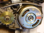
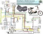
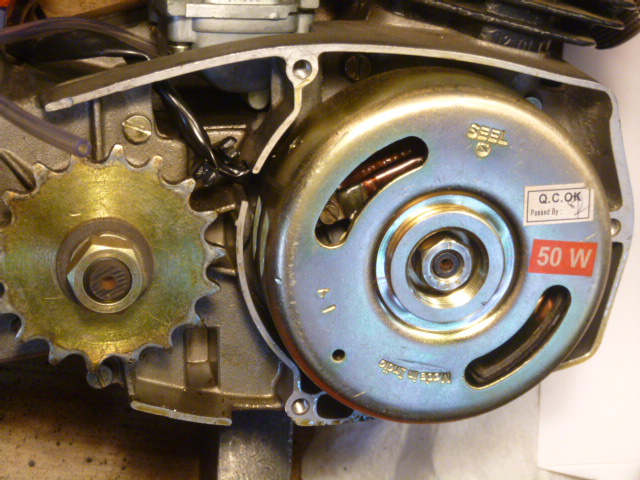
Avanti Autopower motor
Seel 4-wire 50 watt CDI
magneto, made in India
Avanti Wiring: Early 2000’s Avanti mopeds have a 90mm 50W Seel magneto, made in India, with modern CDI electronic ignition. Mont and Autopower have 12VAC one-wire for all lights, with an electronic voltage (shunt) regulator. Kobra has 12VAC on 3 separate lighting wires, with no external regulator.
Avanti controls are copies of late 1980’s Italian made Domino controls, used on Trac, Tomos, Derbi. The switches are copies of late 1980’s Italian made CEV switches, that integrate (fit into) the mounts for the controls (brakes, start, and throttle). The switch buttons use the same white international icons, rather than words.
The original switches for domestic (India) models did not have a handlebar mounted engine stop switch, reachable by the right thumb while holding handlebar grip. The older wiring diagram for Kobra shows this. Only the key on the dash would turn off the motor. But on at least the Supersport model, and maybe also on some Autopowers and Monts, they made the right side headlight high-low beam switch into a engine stop switch, in order to meet the US DOT requirement. This has been the source of confusion. (Turn on the high beam or it won’t start?)
These three wirings took 24 hours to interpret, colorize, re-draw and clean up. The originals were very rough.
B=====================
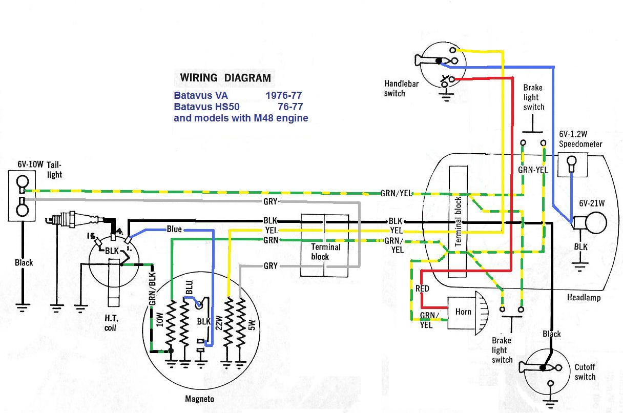
Batavus VA, HS50
Mobat, Bronco, Starflite
without turn signals
1976-78, M48 engine
Bosch 5-wire magneto
internal ignition ground
Batavus VA, HS50
Mobat, Bronco, Starflite
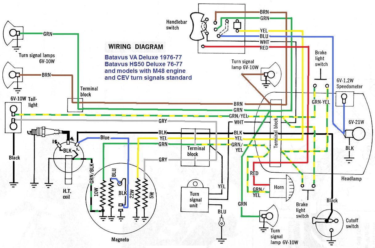
deluxe w/turn signals
1976-78, M48 engine
Bosch 5-wire magneto
internal ignition ground
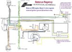
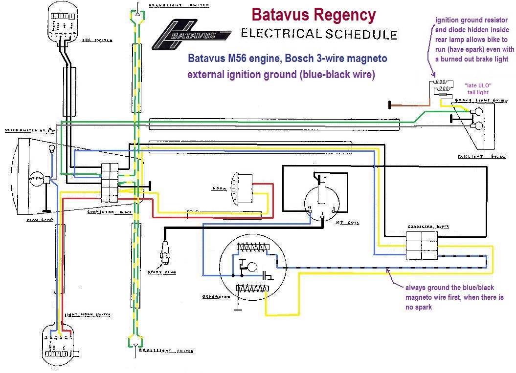
Batavus Regency Wiring
& Regency VA, 1978-80
Batavus M56 engine
Bosch 3-wire magneto
external ignition ground
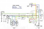
Batavus Wiring (early): The 1976-78 models with Laura M48 engine have a 90mm Bosch 5-wire magneto on the right. Those have an internal ignition ground. None of the lights matter for the ignition to have spark. Head light (yellow), tail light (grey), and brake light (green) each have their own generator coils.
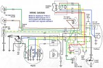
Batavus Wiring (late): The 1978-80 models with Laura M56 engine have a 80mm Bosch 3-wire magneto on the left side. Those have an external ignition ground. That blue/black wire powers the brake light. Consequently there is a special brake light resistor inside the light. While the early ULO 2-bulb tail light did not have a facility for holding a resistor, the later ULO 2-bulb tail light did. In fact there was not just a resistor, but a small circuit board with a nichrome-wire-coil resistor, and a diode. Otherwise the ignition looses spark if the blue/black becomes disconnected.
Battery Wire Versions
Taiwan 6V Mopeds
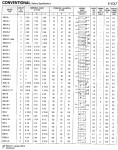
6 Volt Battery Chart
by Yuasa (2008)
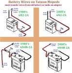
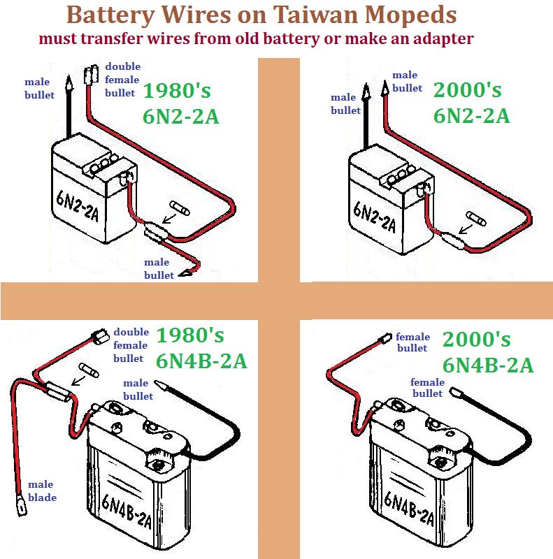
Battery Wires: For vintage Taiwan-made mopeds with 6 volt batteries, General, Lazer, Angel, Speed Bird, Indian, AMS, Clinton, Grycner, and others, getting the correct battery, 6N2-2A or 6N4B-2A is easier than getting the correct battery wires. In the 1980’s, new replacement batteries had vintage moped wires (double female bullet and male blade or bullet, male bullet). In the 1990’s and 2000’s the replacement battery wires changed, see illustration. In the 2010’s the wires changed again to “universal” (female bullet, female bullet plus an assortment of plug-in adapter wires, all bullet connectors). But the assortment does not contain enough to make vintage moped battery wires. To make those from the assortment, cutting, soldering, and shrink-wrapping is required.
Some vintage mopeds have had the bike’s wires adapted to accept a modern battery. Because of so many possible wires, since the 1990’s Myrons has always transferred the old battery wires onto the new battery, whenever the old wires were available. When unavailable, adapter wires were made, mostly from wire scraps. So many have been made, that almost no traces of the old style battery wires survive at Myrons Mopeds, out of hundreds of moped wire scraps.
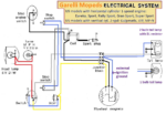
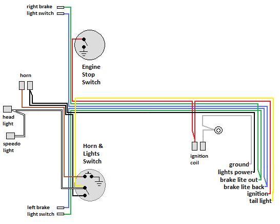
Benelli Wiring: The Benelli G2 moped has a Dansi 3-wire 80mm magneto, with an external ignition ground on the green wire, ignition on the red wire, and lights on the black wire. The Benelli Dynamo mini motorcycle also has a Dansi magneto. More on Benelli soon …
Bianchi Wiring: Bianchi mopeds, US models with Morini MO1 engines, all have Dansi magneto type 101732. This magneto is essentially the same as the 101765 3-wire 2-coil, with external ignition ground on the green wire. Ground the green wire to get spark before suspecting anything else.
C=====================
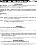
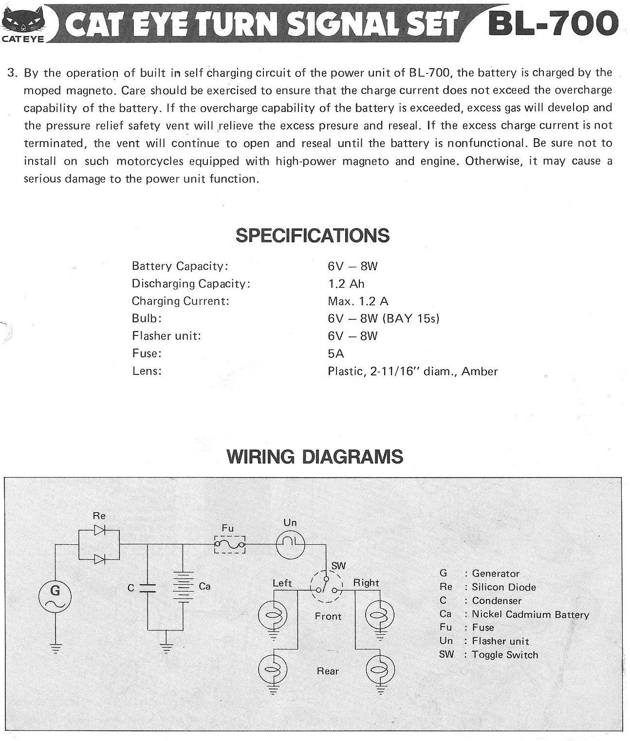
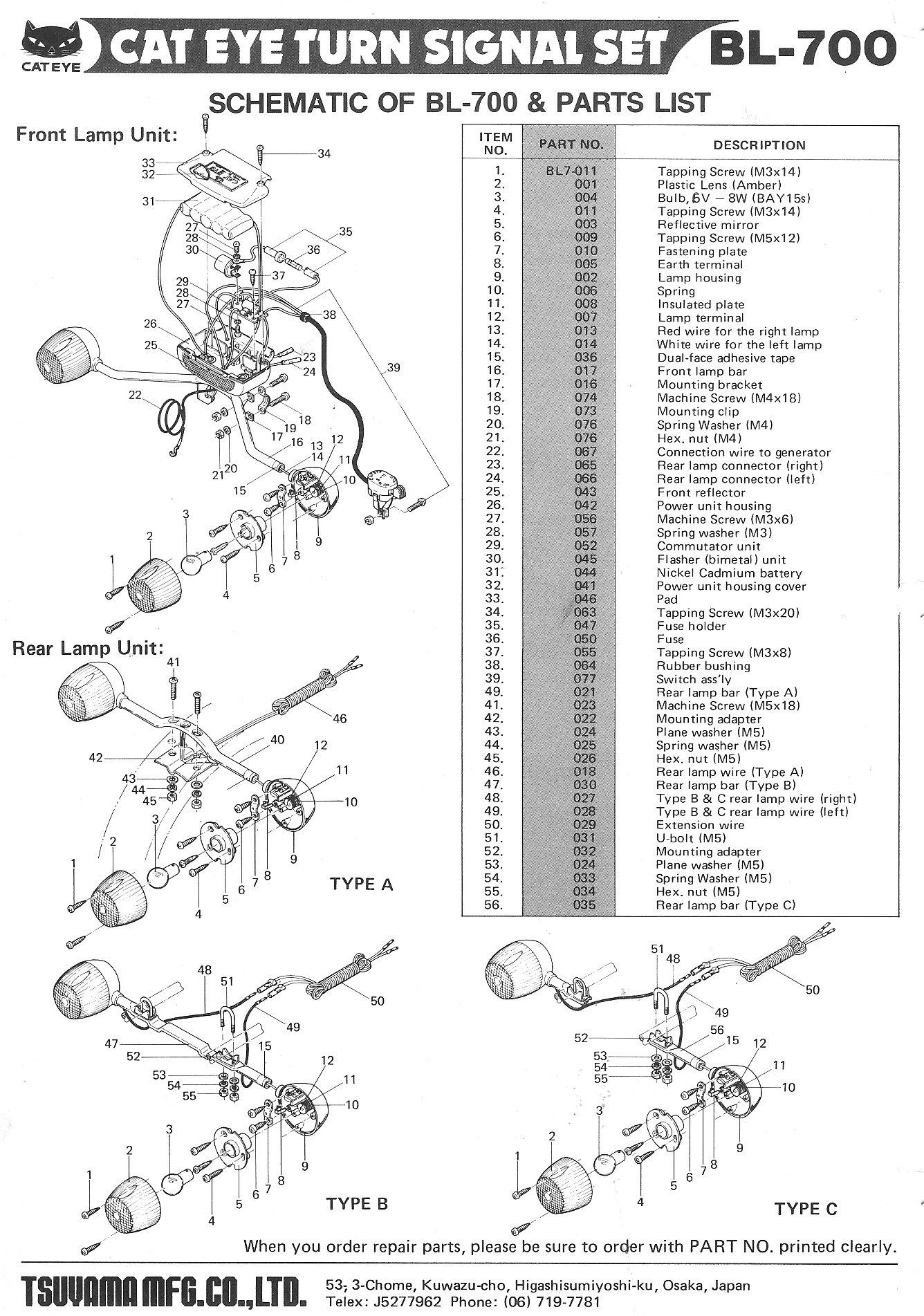
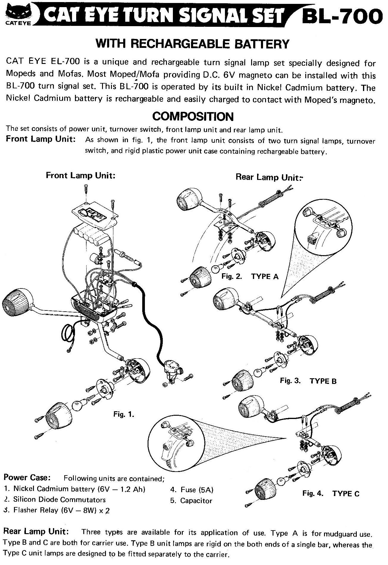
Cateye Turn Signals: Cateye turn signal kits, made in Japan, were an add-on accessory. They had a rechargeable 5.5 volt Ni-Cad battery pack, mounted with the front two lights on a chrome bar that clamped onto a moped handlebar. All of those original batteries died in the early 1990’s.
Cat Eye BL700
Turn Signal Set p1

Cat Eye BL700
Turn Signal Set p2

Cat Eye BL700
Turn Signals p3

Cat Eye BL700
Turn Signals p4
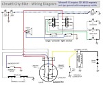
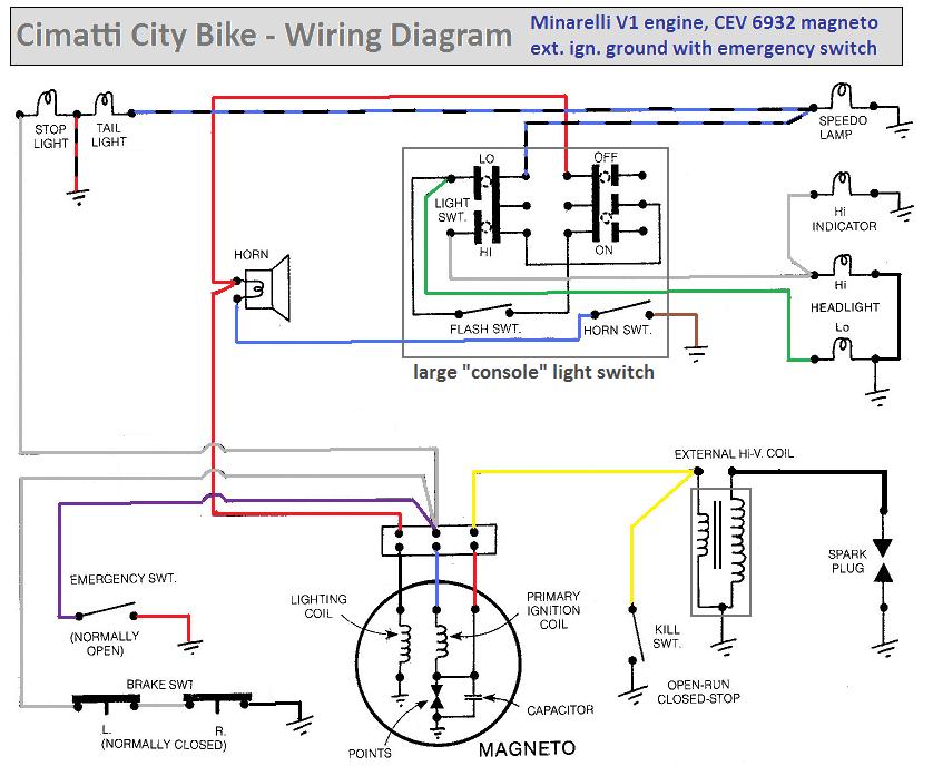
Cimatti City Bike Wiring
CEV 3-wire magneto
external ignition ground
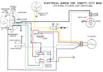
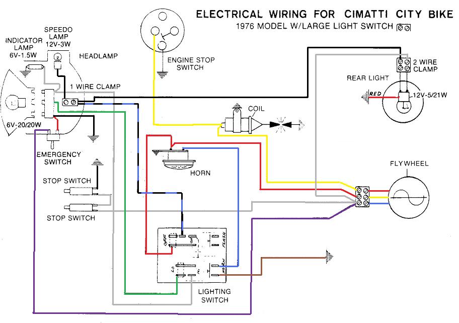
Cimatti City Bike with large console light switch
CEV 3-wire magneto
external ignition ground
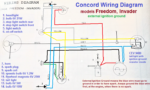
Concord Wiring
1980 Freedom , Invader
CEV 3-wire magneto external ignition ground
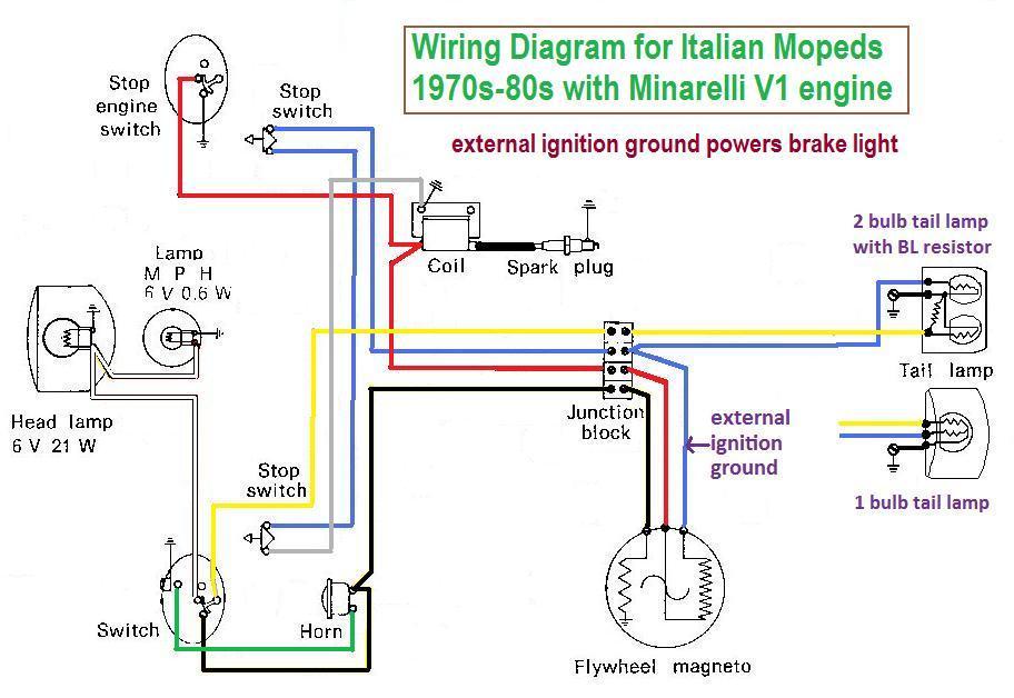
Cimatti Wiring: Cimatti, with the Minarelli V1 engine, has functionally the same as the “Minarelli Wiring”, except for the high-low beam headlight, the console light/horn switch, and the secret toggle switch under the headlight that grounds the blue wire when in the forward position.
Concord (Fantic) Wiring: Concord mopeds with Minarelli V1 engines have “Minarelli Wiring”. The ignition source ground powers the brake light and must be grounded to run. There is a secret resistor inside the tail light. When that burns out the engine dies when the brakes are applied.
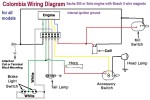
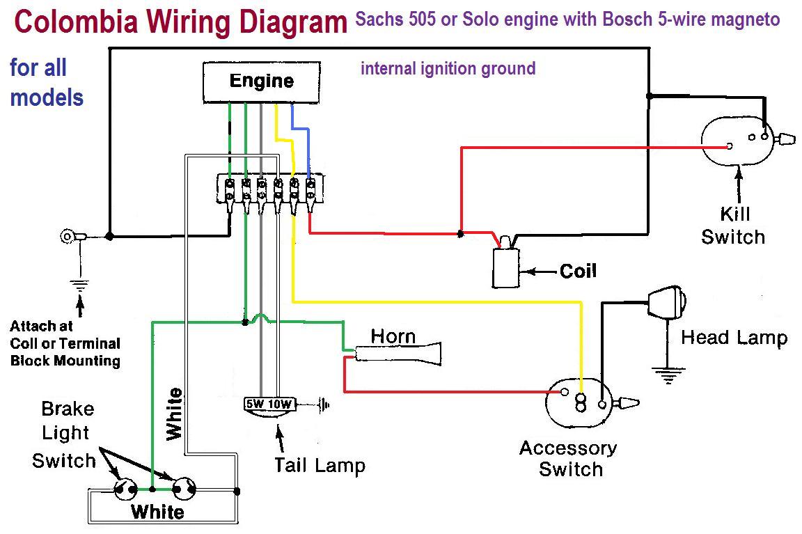
Colombia Wiring Diagram
for all moped models
Sachs 505 or Solo engine
Bosch 5-wire magneto
internal ignition ground
Colombia Wiring: American-made Colombia mopeds can have two different frames, mono-tube and stamped sheet, and two different engines, Sachs 505 or Solo belt drive. But they all have the same Bosch 5-wire 90mm magneto, same wiring and electrical equipment, except for the headlight. Blue is ignition, green and green/black are brake light, yellow is head light, and grey is tail light.
Invisible Forces: Notice that on the Colombia (and others) the tail light gray wire goes straight from the generator/magneto to the light, and not through the light switch. You would think the tail light would then stay on all the time. The small tail light generating coil is close to the larger head light generating coil. Somehow the magnetic field changes around the head light coil when the light is switched on, and that energizes the nearby tail light coil. So the tail light only works when the head light is working. This prevents tail light burn out caused by overload from a burned out headlight. On other 70’s mopeds, when their head light burns out, the tail light gets super bright, and dies.
Furthermore on mopeds with a Bosch 90mm magneto with grey tail light wire, such as Puch, Batavus, Colombia, the headlight bulb is preferably a 6 volt 21 watt (#1129). If it’s a 12 volt 21 watt (#1156), the headlight won’t be as bright, and since it passes less current, the tail light won’t be as bright either. That’s weird. Besides that the tail light bulb needs to be a 6 volt 5 watt #63, or else it will be dim, especially at idle.
D=====================
Daelim Wiring: Daelim Motor Corp (DMC) made Trac mopeds for the US in the 1980’s. See Trac Wiring.

Dansi magnetos
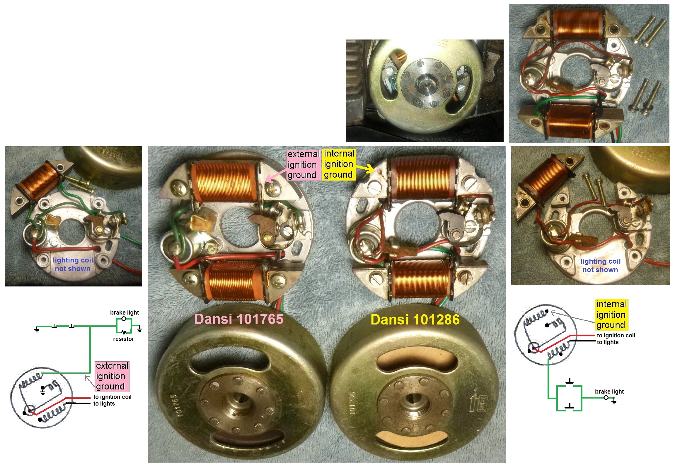
Dansi Magneto: These 3-wire magnetos are used on Benelli, Morini and Rizzato moped engines. Dansi magnetos are included here in wirings because of the number that is stamped onto the 80mm ID flywheel. That number determines the brake light wiring, brake light switches, and tail/brake light type, and more importantly, whether or not it has a “secret” wire that needs to be grounded. Dansi 101286 (anti-clockwise) and 101441 (clockwise) wires are: red = ignition, black = lights, green = brake light. Dansi 101765 (anti-clockwise) and 101732 (anti-clockwise?) wires are: red = ignition, black = lights, green = ignition ground (brake light). If you have an external ignition ground type 101765 or 101732, always ground the green wire first, when checking for spark. See Morini Wiring.

Demm Smily
Demm Wiring: Demm Smily, US models 1976-78 have Demm one-speed engines with CEV 6933 magnetos. The blue magneto wire is an ignition ground that also powers the brake light.
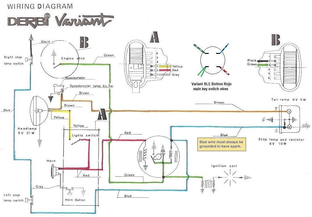
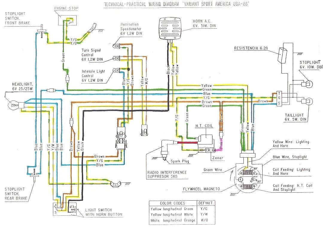
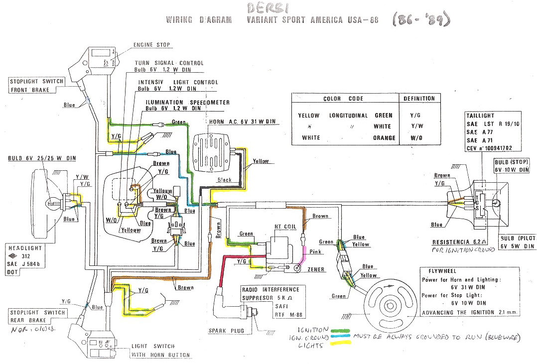
Derbi Wiring: Derbi mopeds, US models 1976-1989, except the DS50, have Motoplat 3-wire magnetos with points, and an external ignition ground on the blue wire powering the brake light. Inside the tail/brake light is a secret hidden ignition ground resistor. If that goes bad, or the wire leading to it, the ignition will loose spark when the brakes are applied. If any of the brake switch wires are also disconnected, then there will no spark all the time. The front ignition ground junction is on the right headlight mount, which is floating in rubber. The rear ignition ground is on the left rear fender bolt, underneath. Both of those places get corroded or loose. Ground the blue wire from the engine first, when checking for spark. Then all those rusty loose grounds don’t matter. That disables the brake light, for emergency or troubleshooting.
Derbi Variant 1976-86
SL, SLE, RD50, Laguna
Motoplat 3-wire magneto
external ignition ground
Derbi Variant Sport 86-89
6V AC voltage regulator
Motoplat 3-wire magneto
external ignition ground
Derbi Variant Sport 86-89
6V AC voltage regulator
Motoplat 3-wire magneto
external ignition ground
Derbi DS50 1987-89
scooter has floor & pedals
12V AC voltage regulator
Motoplat CDI magneto
also with electric start
E=====================
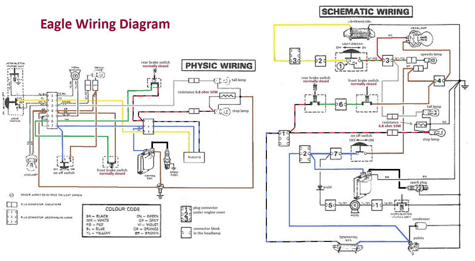
Eagle I, II, and III Wiring
Bosch 3-wire magneto
external ignition ground
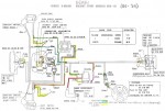
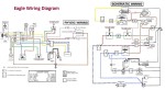
Eagle Wiring: Eagle mopeds were made by Hercules in about 1980-82. Eagle I and II are Sachs Suburbans (I has spoke wheels, II has mags), and Eagle III is a Sachs Prima G3 (top tank). They have a Sachs 505 one speed engine (1D for 30mph, 1A for 25mph, 1B for 20mph) with a Bosch 3-wire magneto, external ignition ground. Always ground the blue black magneto wire first if there is no spark. See Sachs Wiring for a way better version of this wiring diagram.
F=====================
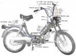
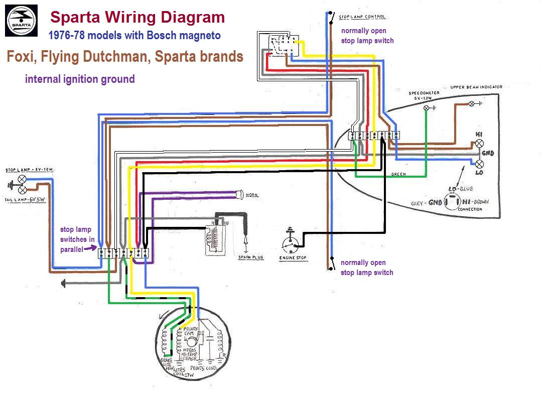
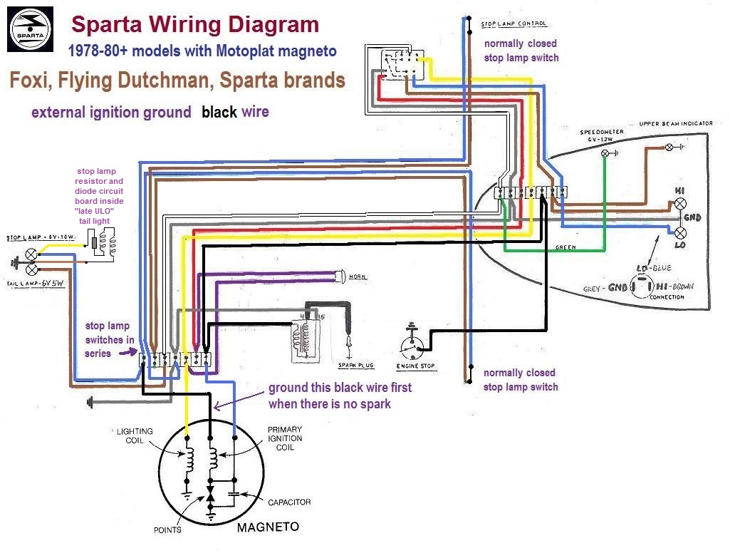
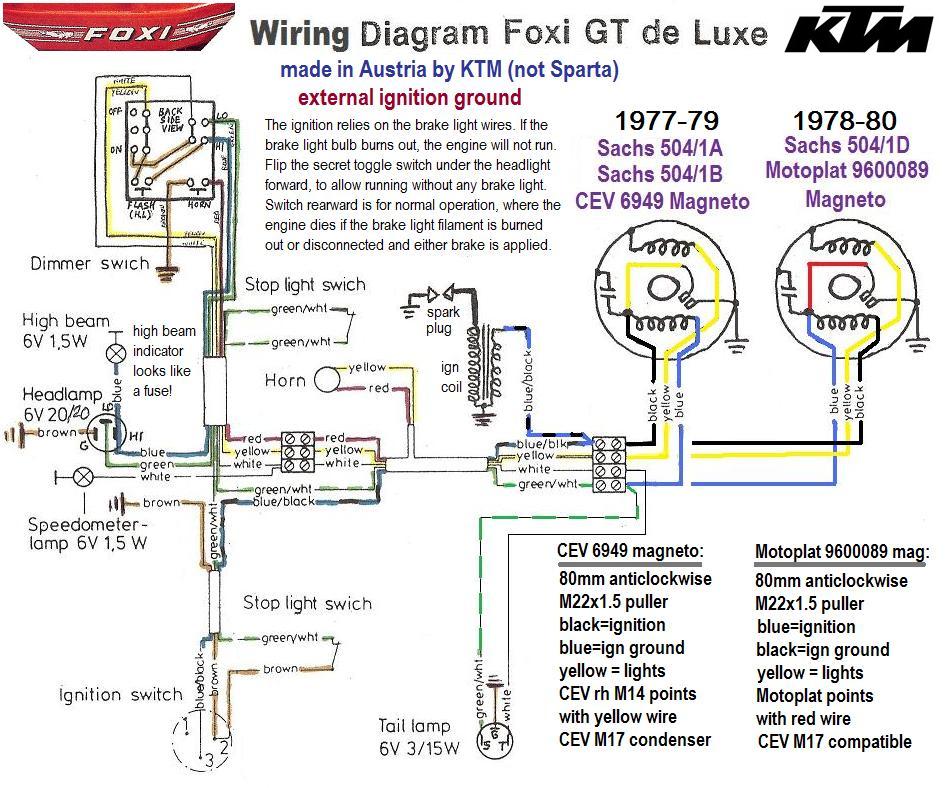
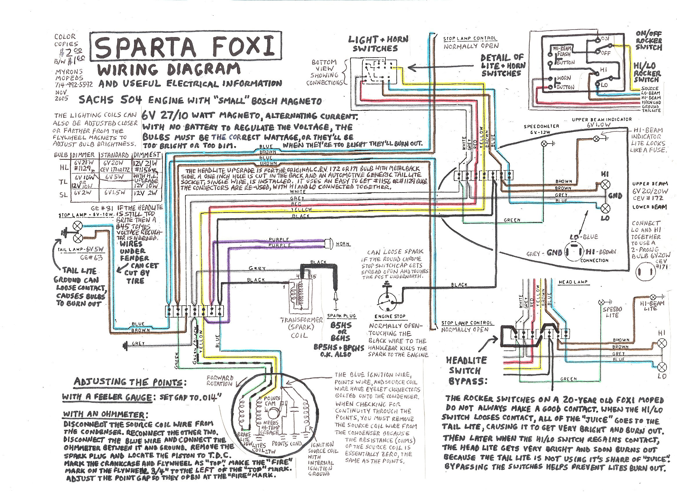
Foxi Wiring: There are actually four Foxi moped models, each made in a different country, and each with a different wiring. 1) Sparta Foxi, made in Holland, see Sparta Wiring. 2) KTM Foxi, made in Germany, see KTM Wiring. 3) Testi Foxi, made in Italy, see Minarelli Wiring. 4) Jui Li Foxi, made in Taiwan, see General Wiring.

Sparta Foxi, F Dutchman
’76-78 (made by Sparta)
Bosch 4-wire magneto
internal ignition ground
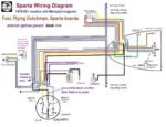
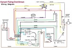
Sparta Flying Dutchman
’78-81 (made by Sparta)
Motoplat 3-wire magneto
external ignition ground
KTM Foxi (US model)
CEV or Motoplat magneto
external ignition ground
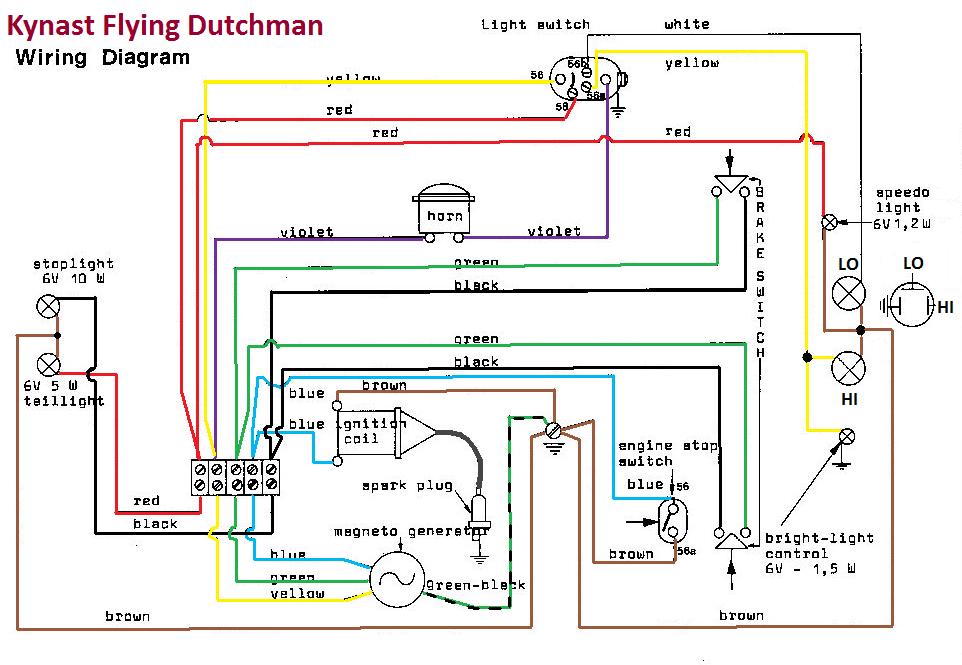
Kynast Flying Dutchman
(made by Kynast)
Bosch 4-wire magneto
internal ignition ground
Flying Dutchman Wiring: There are two models, Kynast (Germany) and Sparta (Holland). See also those names for more info.
Free Spirit Wiring: The Free Spirit line was sold by Sears department stores in 1978-81. They did not say Sears anywhere on the bike. In fact there are no brand markings or names anywhere, except the ID plate and the back of the seat, that says “Free Spirit”. See Sears Free Spirit Wiring.
G=====================
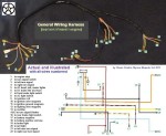
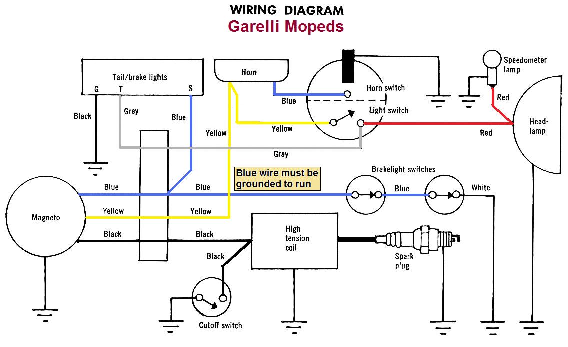
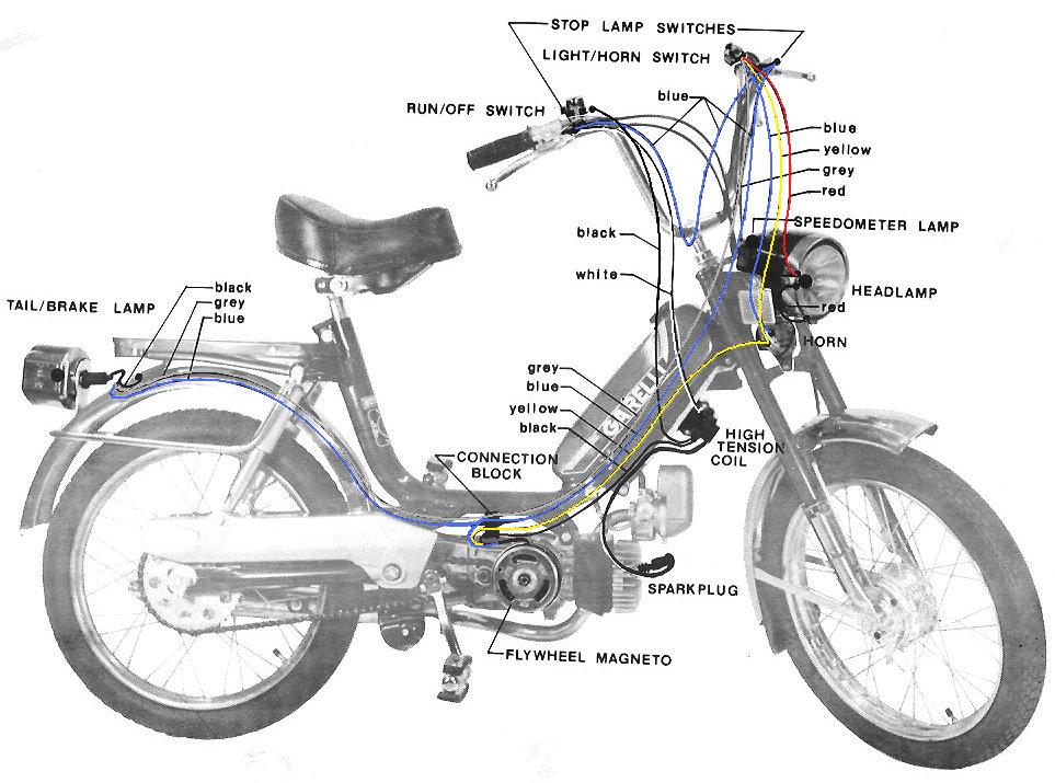
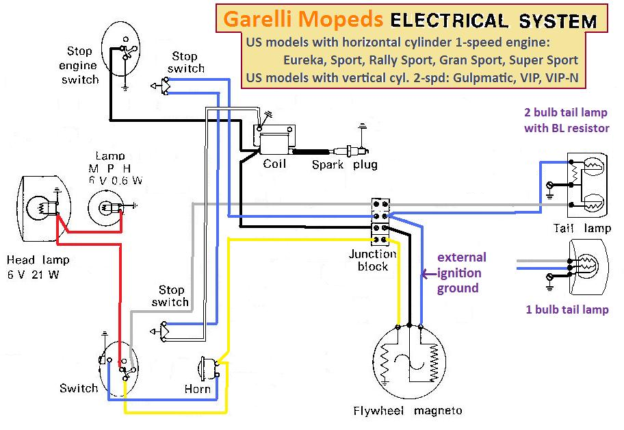
Garelli Wiring Diagrams: All have CEV 3-wire magnetos with external ignition ground powering the brake light. Garelli wiring is functionally the same as “Minarelli” Wiring on many Italian mopeds. Only some of the wire colors and connector or switch styles are different.
Garelli Wiring Simplified
US models 1976-86
Garelli Wiring Actual
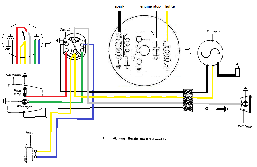
Garelli Wiring Diagram
CEV 3-wire magneto
external ign. ground
1970’s Garelli Eureka and Katia (UK models)
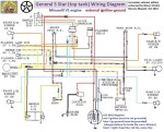
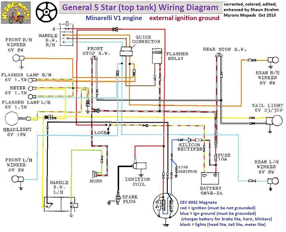
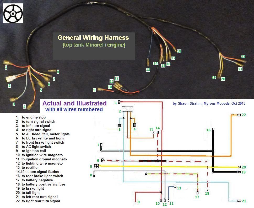
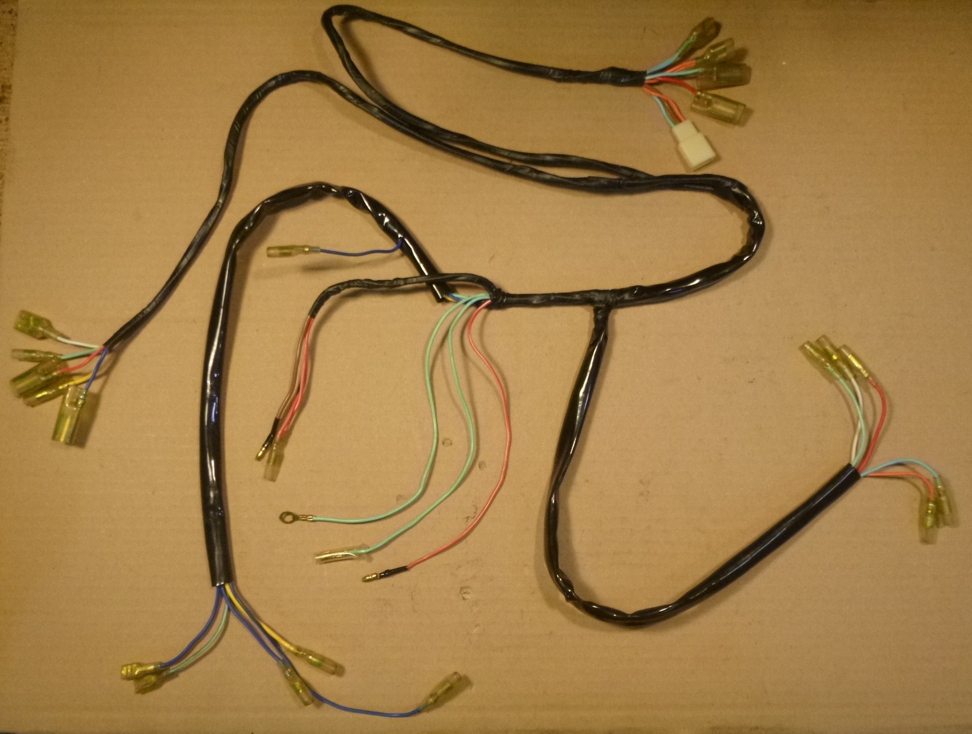
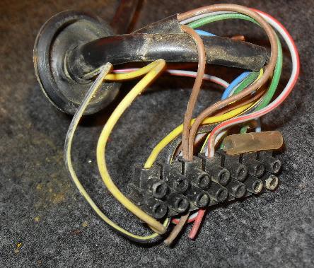
General Wiring Diagrams: There has been confusion for years, because of 1) mistakes in the original wirings, 2) wiring in some models not agreeing with the original owners manual, 3) different brand names and alias names for the Jui Li, Her Chee, or Tsing Hua made mopeds, 4) lack of coverage of wiring issues in the service manuals (perhaps because different engines were optional, the engine manuals were separate and not integrated into the main manual), and 5) different versions were produced, sometimes without documentation. The wirings below come from actual wiring harness replacement parts, or actual mopeds or scraps of them. Showing the real wires alongside the diagram for them proves that these corrected wirings are accurate, even though some things might contradict some original wiring diagrams.
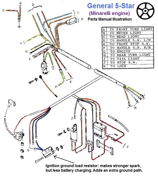
General 5-Star Wiring
top tank Minarelli V1 eng
CEV 3-wire magneto
external ignition ground
General Wiring Harness
top tank Minarelli engine
CEV 3-wire magneto
external ignition ground
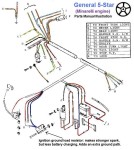
General 5-Star Actual
(top tank Minarelli)
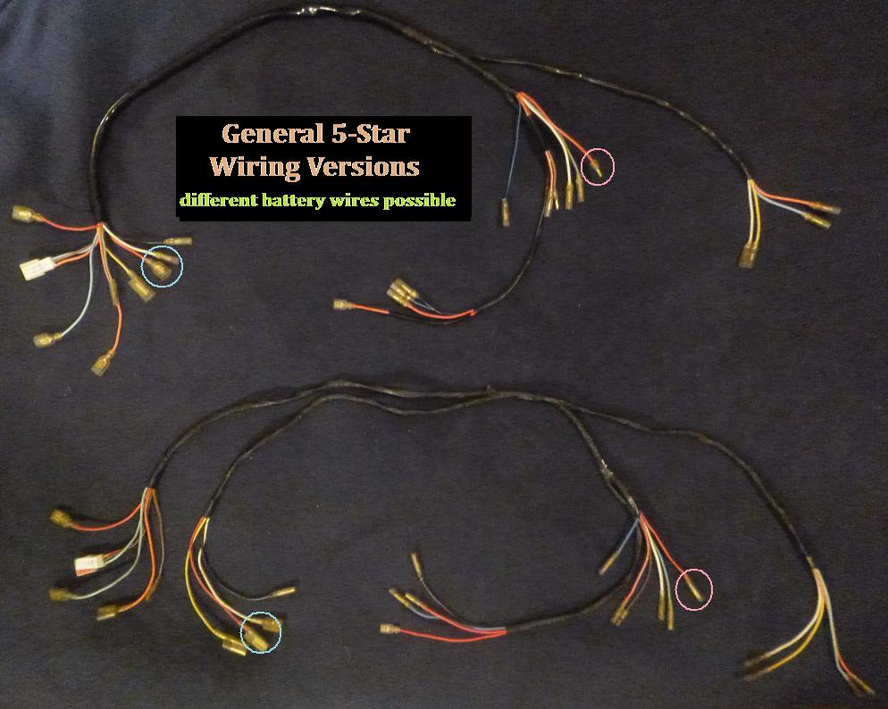
General 5-Star Versions
battery wire, pink circle
top – male bullet
bottom-female bullet
General Brake Light Switches: General 5 Star (top tank) has the brake light switches that screw into the levers. General 5 Star ST (step thru) has a front brake light switch in the cable, and a foot brake switch. Other kinds (Lazer?) have both front and rear brake light switches built into the cables. Some of the wirings have an unused female bullet connector on the white wire, to allow either kind of brake light switch.
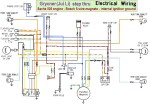
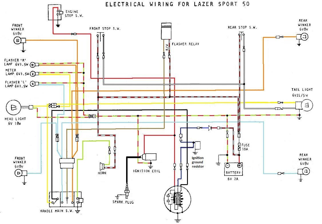
General and Lazer (Jui Li) top tank mopeds (Minarelli V1 engine with CEV 6932 magneto with external ignition ground): General 5-Star and Lazer Sport 50 have 97% the same wiring, except for: 1) General has a steering lock key switch, that kills the spark and un-grounds the battery when the key is removed, 2) Lazer has an additional lite green and red ground wire in the harness, 3) Lazer has a 6N2-2A battery, while General has a 6N4B-2A battery, twice the amp-hours and wider.
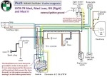
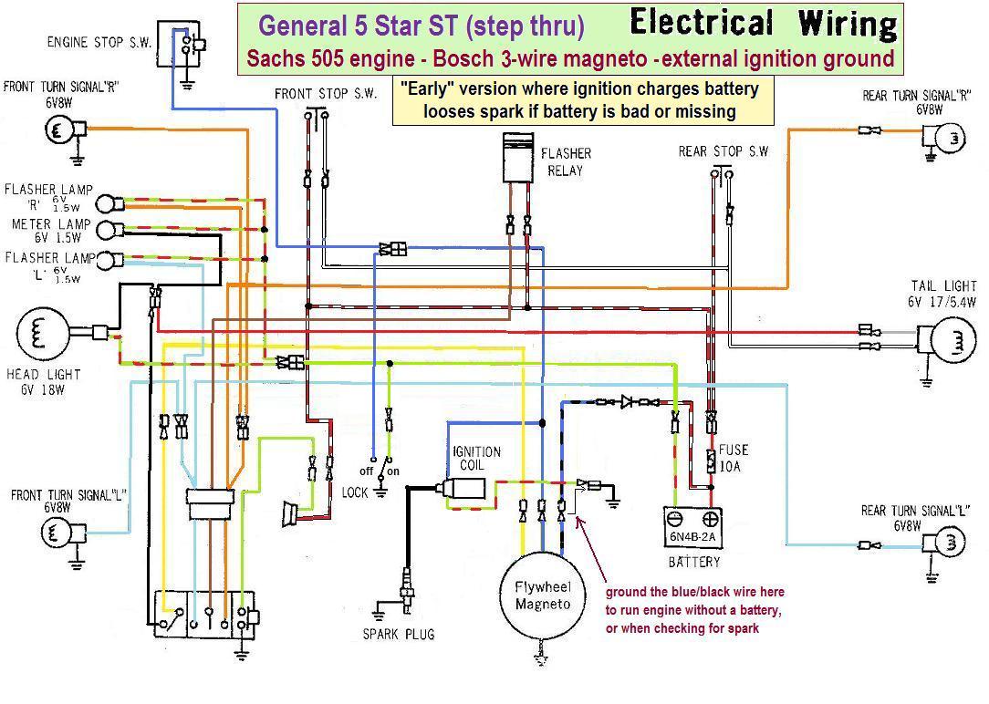
General 5 Star “early”
Sachs 505 foot brake
Bosch 3-wire magneto
external ignition ground

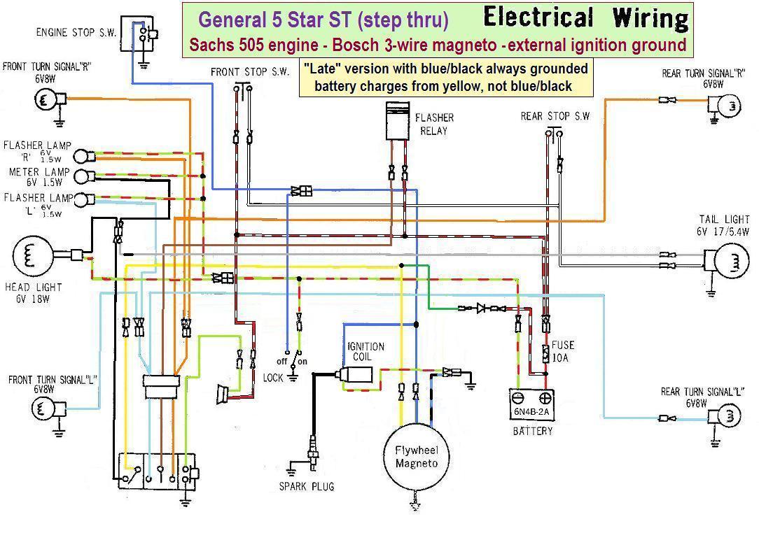
General 5 Star “late”
Sachs 505 foot brake
Bosch 3-wire magneto
ext ign gnd (always gnd)

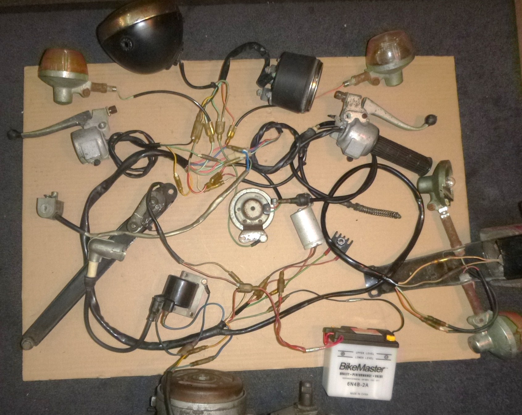
General ST “late” Actual
Sachs 505/1A foot brake
Bosch 3-wire magneto

General-compatible
new, unknown origin
for Bosch 3-wire magneto
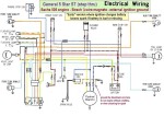
General 5 Star ST step thru mopeds (Sachs 505 engine), made by Jui Li: General 5-Star ST wiring “early” version is functionally the same as the top tank models, because of the 3-wire Bosch magneto, configured to charge the battery from the ignition ground. With this version, if you removed the battery, or it went bad from sitting, the ignition would loose spark. The General 5-Star ST wiring “late” version instead charges the battery from the main lights wire and has the ignition ground always grounded, so it never looses spark even when the battery is removed. The trade-off for that increase in reliability is a slightly dimmer headlight, which is also a good thing because it helps prevent headlight burn out.
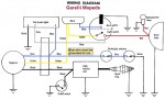
Grycner Wiring Diagram
Sachs 505/1A engine
Bosch 5-wire magneto
internal ignition ground
AMS Wiring Illustrated
Sachs 505/1D engine
Taigene 3-wire magneto
external ignition ground
General look alikes:
Grycner mopeds are identical to General step thru, but have Bosch 5-wire magnetos, with internal ignition ground, and slightly different wiring.
Unbranded generic Jui Li step thru and top tank mopeds are identical to General. Their wiring and magneto is unknown.
AMS Sierra 50 step thru and Tahoe 50 top tank, are made by Her Chee, not Jui Li. They have wiring compatible with General ST, and a Bosch-compatible 3-wire 90mm Taigene magneto. AMS has the later Sachs 505/1D rather than 505/1A.
General Battery Versions: All Generals and Grycners use a 6N4B-2A flat 6 volt battery. Notice in the “General 5 Star Versions” photo above how the original top tank wiring came with different battery wire connectors, either male or female bullet. Besides that the modern replacement batteries have different wires than the original batteries did. See above section “B” about Battery Wires.
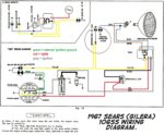
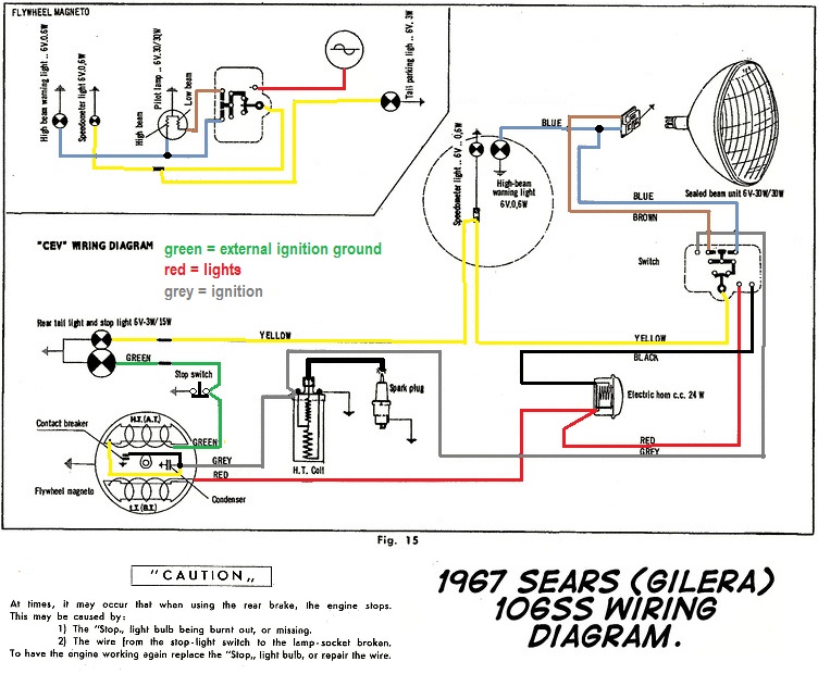
Sears (Gilera) 106 SS
Gilera 106 SS (1967) Sears Allstate (US model) has a CEV 6826 3-wire points magneto with external ignition ground on the green wire. If that wire is disconnected there will be no spark.
H=====================
Harley D. M50, M65
Harley Davidson Wiring: 1965-66 Harley Davidson M50, MS50 models have Dansi ASL222S magnetos. 1967-72 M65, ML65, ML65 Leggero models have a Dansi ASL236NS magnetos. They all have 3 magneto wires, black (ignition), green (ignition ground and brake light) and red (lights). Red and black are opposite from most other Dansi magnetos. Green must be grounded (connected to the frame) in order to have spark. It powers the brake light. If the brake light burns out, the engine will loose spark when the brakes are applied. Any other situation where green to ground is interrupted will cause loss of spark, like wires under the rear fender cut by the tire, loose or rusted fender mounts, loose or rusted bulb contacts, or the tail/brake light connectors loose or corroded. Always ground the green engine wire to eliminate those causes of no spark. That allows the engine to run, but without a brake light.
Hercules Wiring: Hercules mopeds, made in Germany, are also known as Sachs. See Sachs.
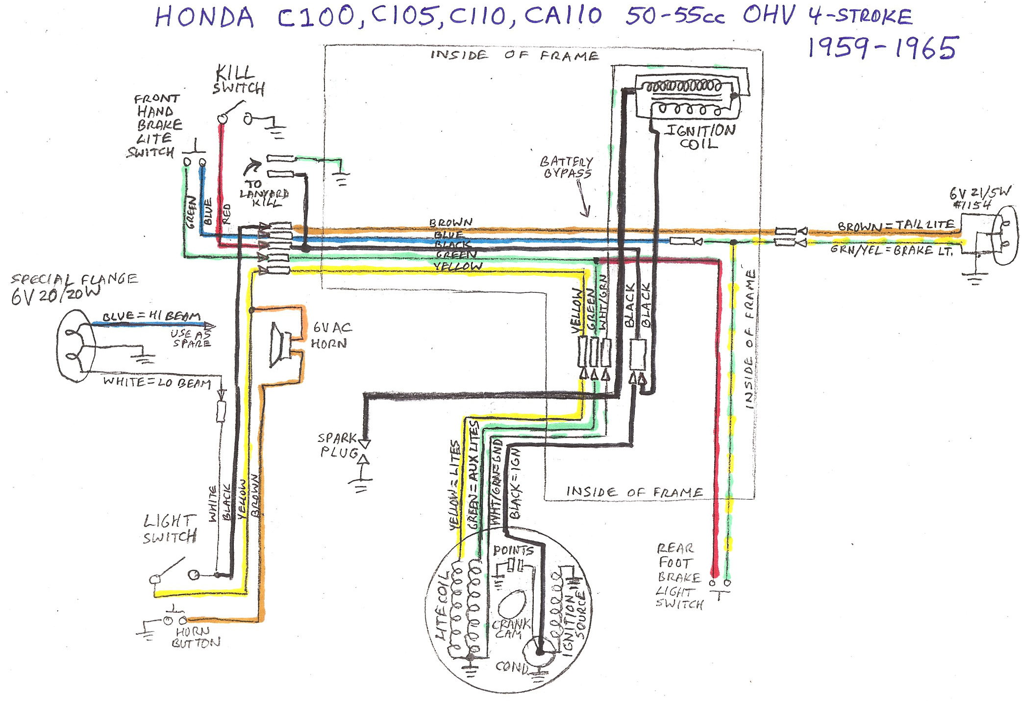
Honda Wiring: Honda has hundreds of small motorcycle models worldwide, with different wirings. These are the USA models (unless stated otherwise) of mopeds and motor-driven cycles. More to follow…
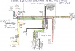
Honda C100 Cub series
CA100, C102, C105,
C105T, C110, CA110T
50 & 55cc 1959-70
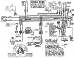
Honda PC50 (US model)
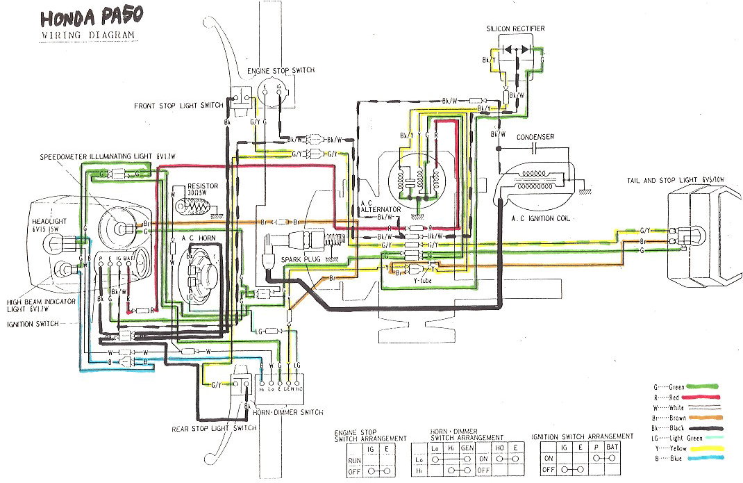
Honda PA50 Hobbit
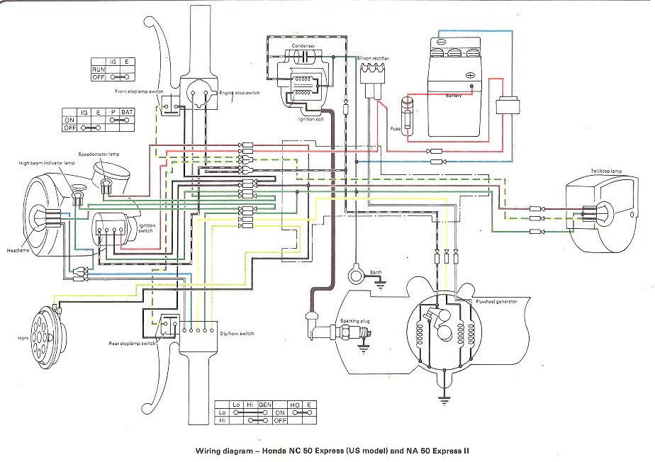
Honda NC50 (US) Express
Honda NA50 Express II
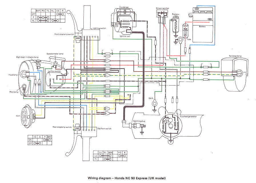
Honda NC50 (UK model)
I=====================
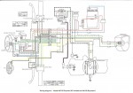
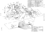
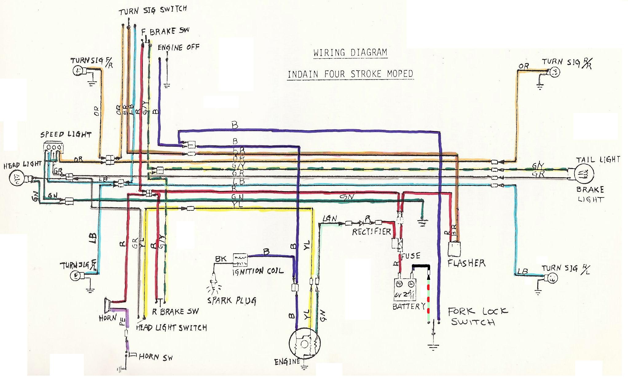
Indian AMI-50 Wiring: Indian AMI-50 was made in Taiwan by Merida or Mira.
Indian AMI-50 Battery Versions: All Indians use a 6N2-2A small 6 volt battery. Modern replacement batteries have different wires than the original batteries did. See section “B” about Battery Wires.
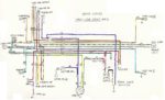
Indian 1978 Wiring
WTEMCO 3-wire magneto
no key switch,
internal ignition ground
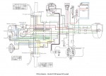
Indian Wiring 1979-84
WTEMCO 3-wire magneto
brake switches normally open, in parallel,
internal ignition ground
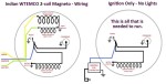
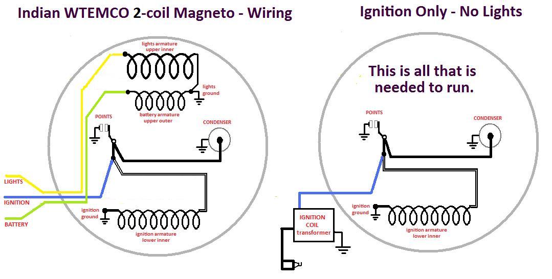
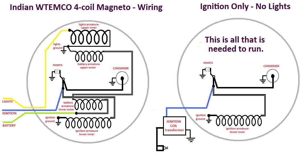
Indian 2-coil Magneto
is actually 3 coil, since
2 are combined into 1
blue=ign, yellow=lites
green=battery charging
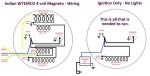
Indian 4-coil Magneto
early models 1978?
2 small battery charge coils are in series, to
make the same 3 outputs

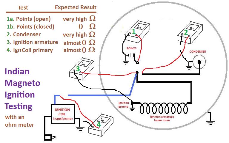
Indian Magneto Testing
Indian ME100 Wiring:
1973 Indian ME100
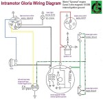
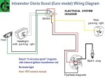
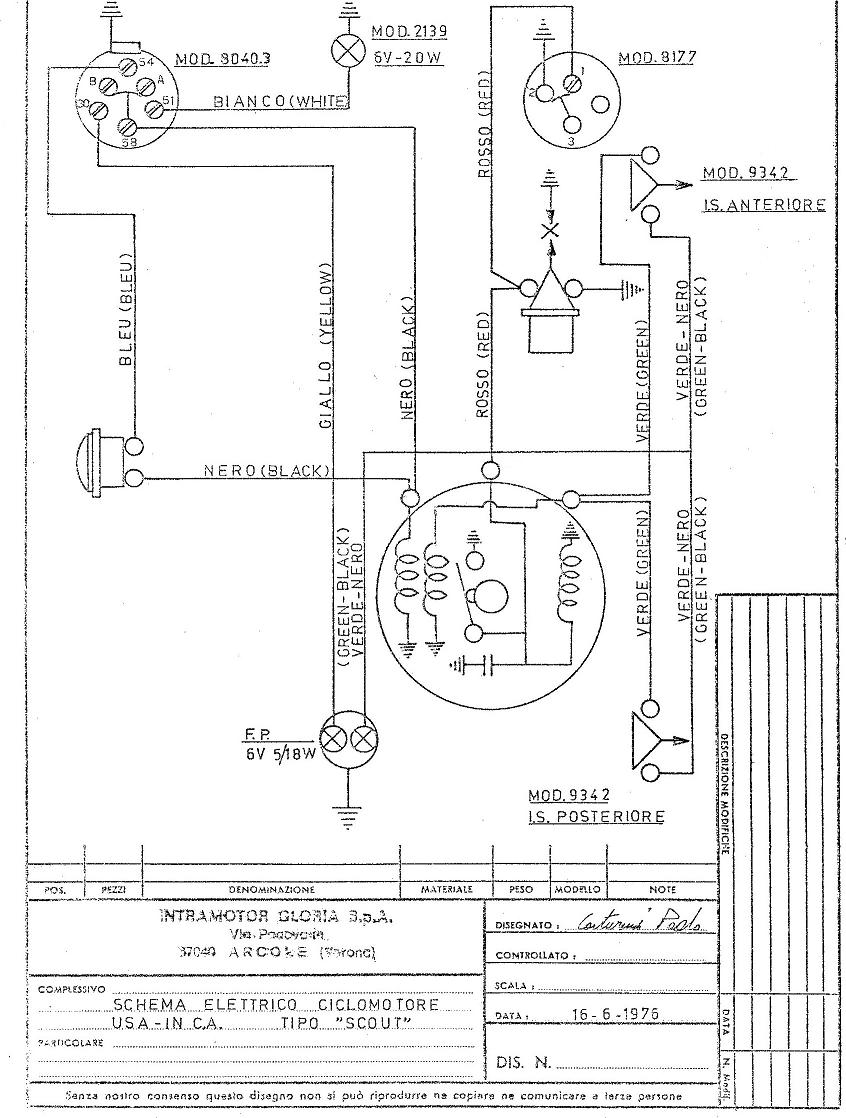
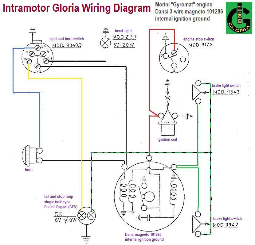
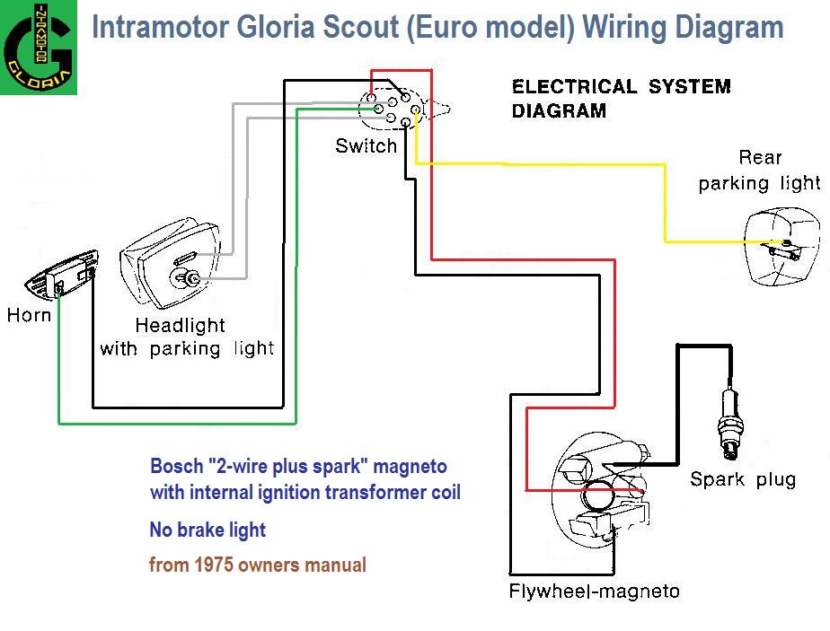
Intramotor Gloria Wiring: Of the 3 or 4 Intramotor Gloria models, Scout, Blanco, Kid and Mini-Kid, only the Scout wiring is shown. The others may or may not be the same, depending on their Dansi magneto type. See “Morini Wiring”.
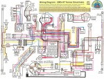
Notice how the Euro model version has no brake light, and one clamp-on switch for lights, horn, and engine stop. Simple!

Intramotor Gloria
Schema Elettrico
Dansi 3-wire mag.
internal ign. gnd
Intramotor Scout
(USA) with brake light
Dansi 3-wire magneto
internal ignition ground
Intramotor Scout
(Euro) no brake lite
one switch for all
Bosch 2-wire+spark
internal ignition ground
J=====================
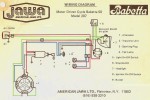
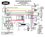
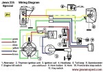
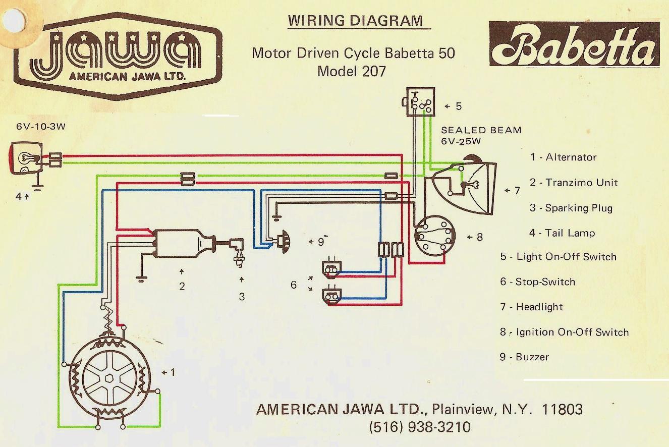
Jawa Babetta 1976-78
model 207.011 (0.9hp)
up to frame # 210999
4-wire internal rotor mag
big red Tranzimo unit
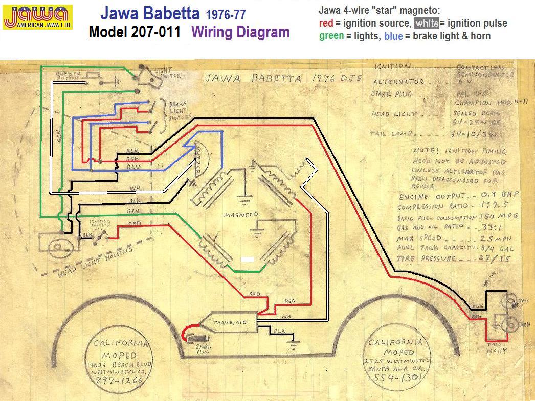
Jawa Babetta 1976-78
diag. by California Moped
model 207.011 (0.9hp)
4-wire int. rotor magneto
big red Tranzimo unit
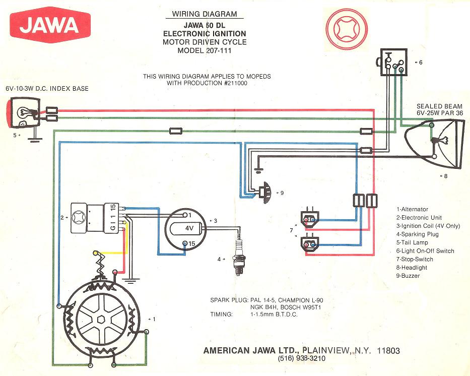
Jawa Wiring: The original Jawa Babetta, with the famous red “Tranzimo” ignition unit (coil with electronic circuit) had 19″ rims was sold in Europe since 1972. Sometime after that the rims became 16″, and the model became also known as the “207”. Starting in 1976, American Jawa sold US versions of the model 207. They had brake lights and engine stop switches. The earliest US Jawa Babetta was the 1976-78 model 207-011, with big red Tranzimo ignition unit visible on the right side above the engine, with it’s high tech thyristor exposed on one end.
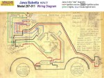
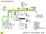
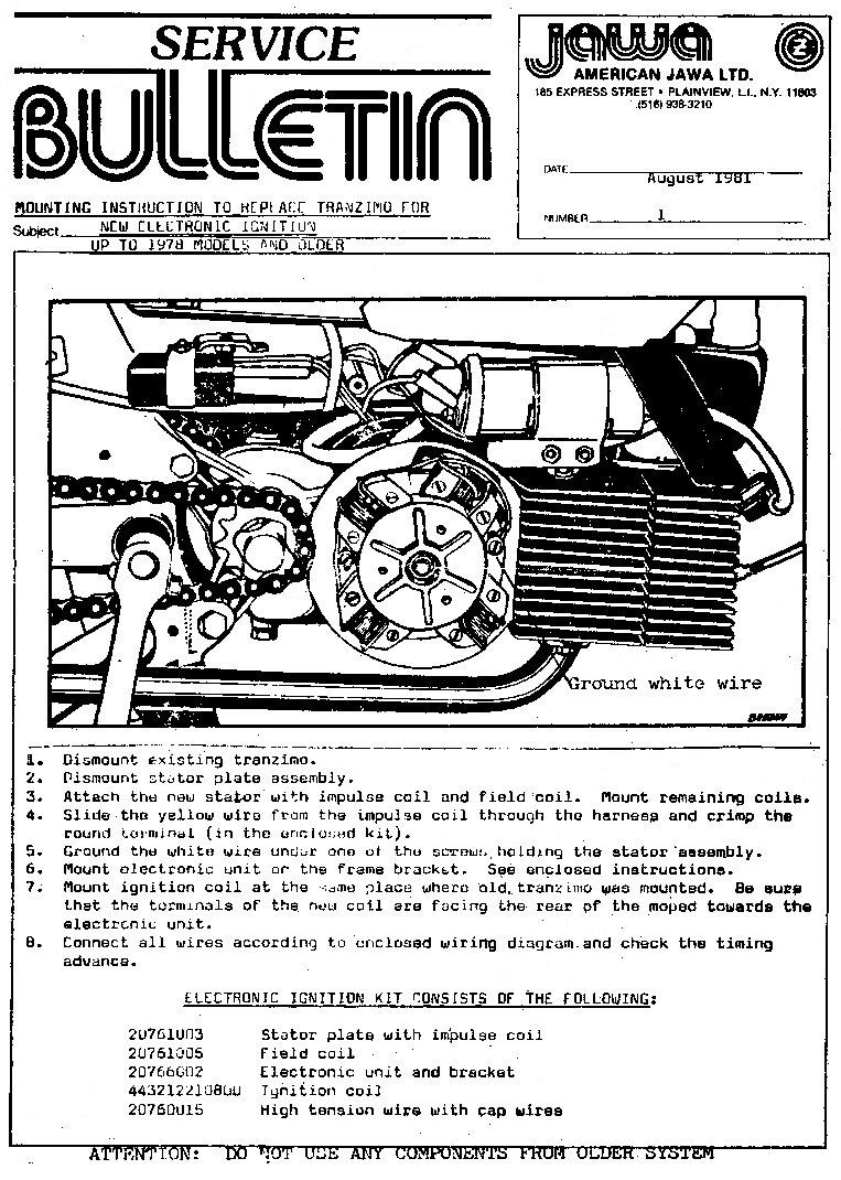
In 1978, starting with frame number 211000, the official US model name changed from Babetta to 50 DL, the model number changed from 207.011 to 207.111, and more importantly, the “big red Tranzimo” thyristor ignition unit and stator changed to the newer “black box with separate metal-can-coil” thyristor ignition unit and stator.
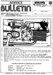
Jawa Aug 1981
Service Bulletin 1
On pre-’79 Jawa,
replace Tranzimo
and stator assy.

Jawa 50 DL 1978
model 207.111 (0.9hp)
frame 211000 to 249999
4-wire int. rotor magneto
black box thyristor unit
metal can-type spark coil
no eng stop switch shown
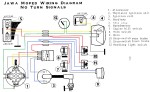
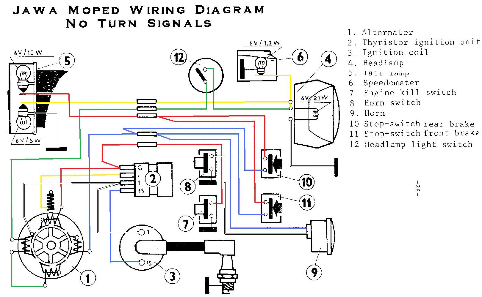
Jawa 50 DL 1978-79
no turn signals model
model 207.111 (0.9hp)
frame 211000 to 249999
4-wire int. rotor magneto
black box + metal can
revised w/ eng stop switch some revised wire colors
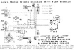
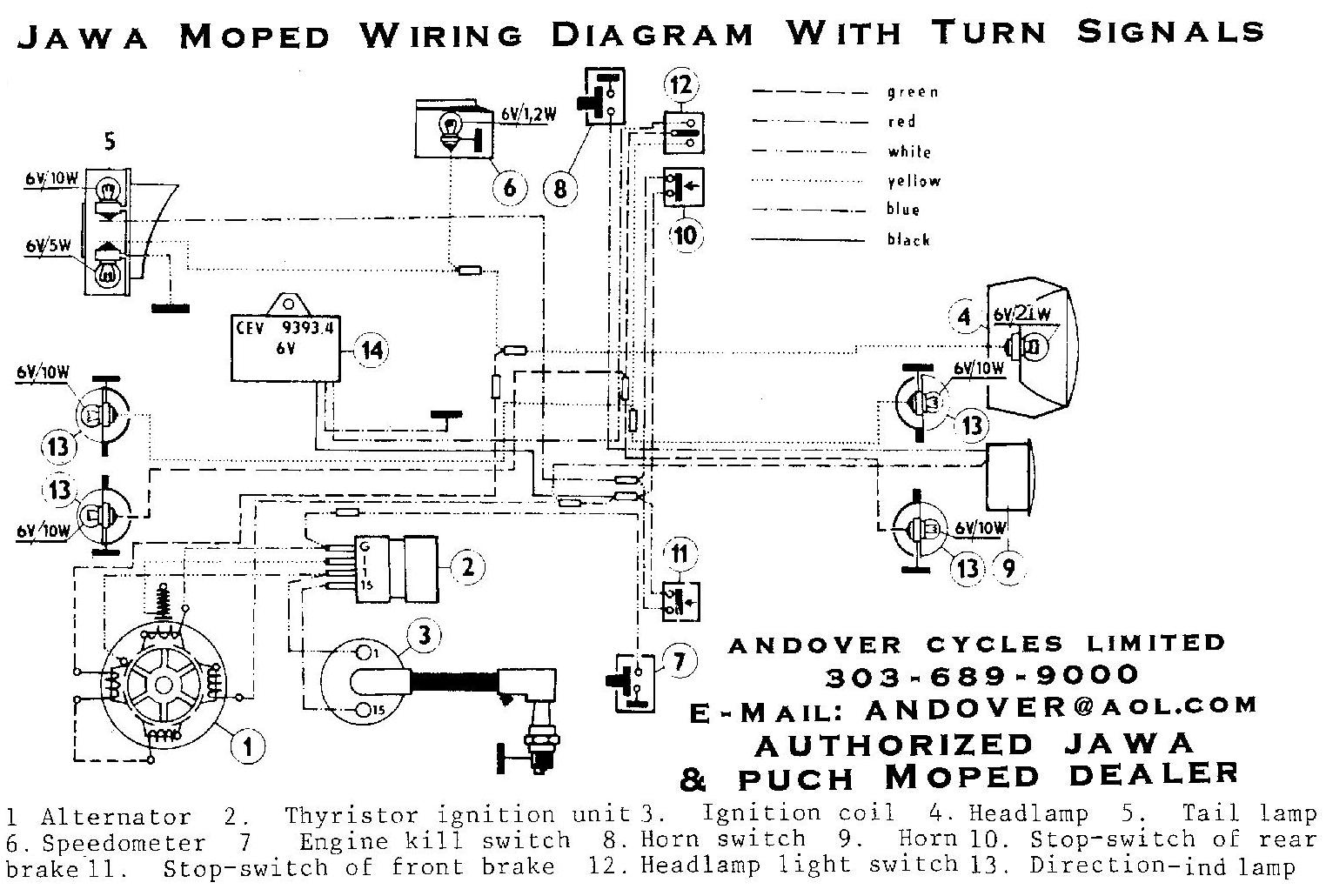
Jawa 50 DLX 1978-79
deluxe with turn signals
model 207.111 (0.9hp)
frame 211000 to 249999
4-wire int. rotor magneto
black box + metal can
Jawa 50 1979-80
207.311 C,DL,DLX
250000 – 349999
same wiring
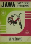
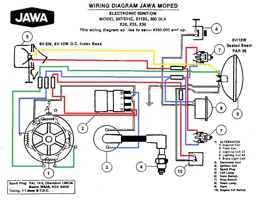
Jawa mopeds 1980-82
207.311 50C,DL 207.300 50 DLX, X20,X25,X30
frame no. 350000-up
4-wire int. rotor magneto
no head light switch
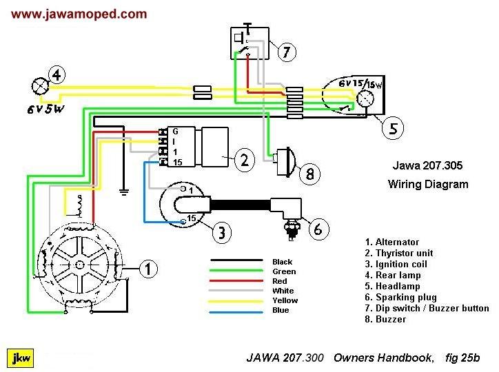
Jawa moped 207.305
no brake light (Euro)
no engine stop switch
In 1979, starting with frame number 250000, the USA models changed to the 207.300 series. The horsepower went up from 0.9 to 1.5. The carburetor changed from Jikov 9mm to Bing 12mm. But the wiring and electrical equipment stayed the same.
In 1980-81, they had new model names, Jawa X30 (30mph 2hp?), X25 (25mph 1.5hp) and X20 (20 mph 1hp). The wiring did not change, but the tail light changed from Peterson to CEV.
In August 1981, American Jawa sent out it’s first service bulletin, telling dealers how to cure the Tranzimo ignition problems once and for all, by replacing with the newer black box thyristor type.
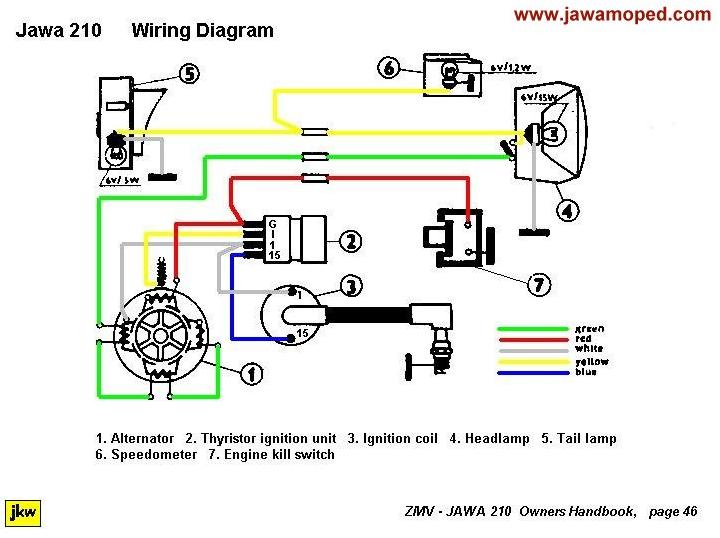
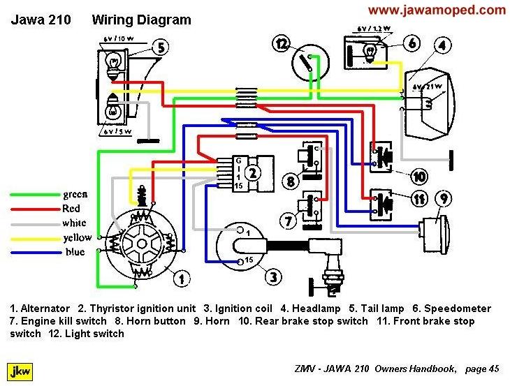
In 1983, an all-new model was indroduced, the Jawa 210. It had a two-speed instead of one speed transmission. It had a new frame and other improvements. In the mid 1980’s the 210 was made in sport and deluxe versions. The wiring did not change on the 210 models for the rest of the 1980’s.
In the late 1980’s, Jawa made models 225 (25mph), 230 (30mph), 230 Breeze (30mph mag wheels). They had 2-speed transmissions, and some minor wiring differences.
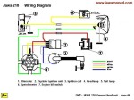
Jawa mopeds 1983-91
210 series (2-speed)
no brake light (Euro)
no turn signals
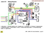
Jawa mopeds 1983-91
210 series (2-speed)
with brake light (USA)
with CEV turn signals
Jawa mopeds 1985-91
225/230 series (2-spd)
with brake light (USA)
no turn signals
Jawa Thyristor: Here is an excellent article on how to replace a burned out Jawa “black box”. There are just three components to buy and solder together, a thyristor, a capacitor, and a diode. Here is an even better article that shows in detail the ignition versions, upgrades, and individual thyristor component replacement options.
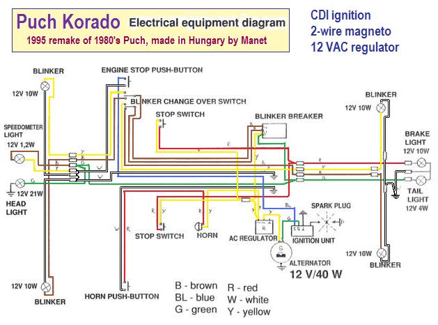
In 1993, the country of Czechoslovakia split into Czech Republic and Slovakia. That was pretty much the end of the old Jawa. Then in the mid 1990’s, Jawa mopeds were re-made in Hungary at the Korado factory. The step thru models were called Babetta, while USA top tank models were called Jawa (1995 Sport, Supersport, Ultrasport). The re-make Jawa/Babetta wiring changed, to be like the 1995 Puch Korado, made in Hungary by Manet, with one wire for all lights and a 12VAC shunt type voltage regulator. See Manet Wiring for that. The last year for the beloved Babetta was 1997. Click here for the full Jawa history.
JC Penney Wiring: JC Penney department stores sold the Pinto and Swinger moped models, made by Kromag. They have Puch engines and 1977-78 Puch (6-wire) wiring, where the blue black horn wire must be grounded to run. See Kromag Wiring.
K=====================
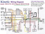
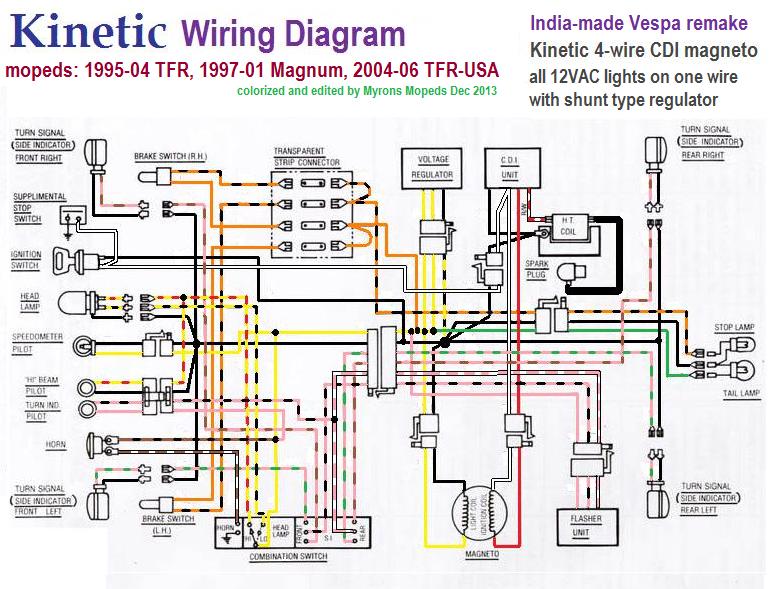
Kinetic (moped) Wiring
India-re-make of a Vespa
4-wire CDI magneto
Kinetic Wiring: Kinetic TFR, Luna TFR, Magnum, and TFR-USA are modern 1990’s-2000’s remakes of a 1970’s-80’s Italian made Vespa(Piaggio) pedal-start mopeds. They have modern electrical wiring, with all lights on one wire and a shunt type voltage regulator. So there is no battery, and no DC anywhere, only 12 volt alternating current. They have modern CDI ignition, no points. The Kinetic Pride is a scooter (with a floor and no pedals) with a battery, electric start, and a different wiring, not shown here.
Korado Wiring: The Korado is a Puch re-make, made by Manet. See Manet Wiring.
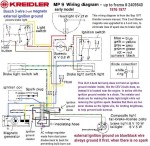
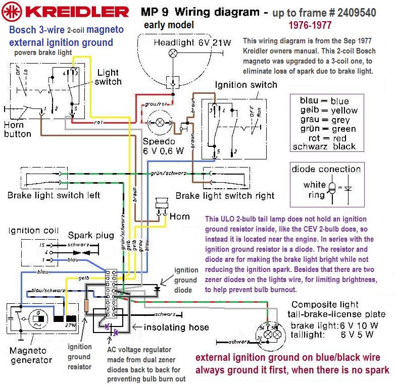
Kreidler Flory MP9(early)
up to frame 2409540
Bosch 3-wire 2-coil mag
external ignition ground
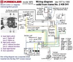
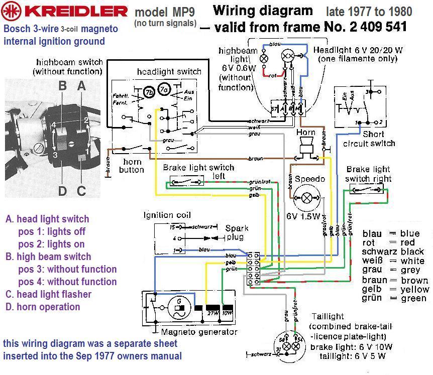
Kreidler Flory MP9 (late)
from about late 1977-on
frame 2409541 and up
Bosch 3-wire 3-coil mag
internal ignition ground

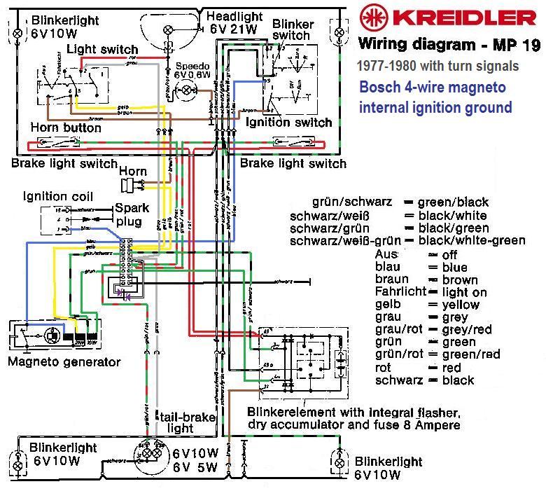
Kreidler Flory MP19
turn signals & mag whls
Bosch 4-wire 3-coil mag
internal ignition ground
Kreidler Wiring: These wirings appeared only in the Kreidler owners manuals, in tiny unreadable print. Now they are deciphered and made easy to follow. Even the mysterious diodes are explained. These 3 took 14 hours to scan in and fix up. Because the US requires a brake light, and requires that the head light not get dim when the brake light is on, that is why they used diodes, for bright lights with less bulb burnout.

Kromag/Sears Wiring
Sears Free Spirit (1-spd)
Puch 1977-78 (6-wire)
external ignition ground
Green/black wire explained: Many Bosch magnetos have a green and black wire that simply goes to ground. Did you ever wonder why they did not just ground it internally? The Kreidler Flory MP19 is one moped that uses the grün/schwarz wire the way Bosch intended it. The green and green/black are inputs to a full wave rectifier, which is the four diodes inside the turn signal power pack. It is for battery charging. If the green black were grounded, it would only be a half wave rectifier, and the battery charging would only be half as much.
Kromag Wiring: Kromag makes the Sears Free Spirit moped line. All Free Spirits have the same wiring and electrical equipment as 1977-78 Puch Maxi (6-wire). The blue/black horn wires need to be connected, or grounded in order to have spark. The external ignition ground is through the clamp of the light/horn switch. Wild!
Kynast Flying Dutchman
Sachs 504/1A or 508/AD
4-wire Bosch magneto
internal ignition ground
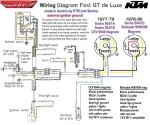
KTM (US model Foxi)
CEV or Motoplat magneto
external ignition ground
KTM (Foxi) Wiring: This wiring is functionally identical to Cimatti, with a hi-lo headlight, console type light and horn switch, external ignition ground running the brake light, and a secret toggle switch under the headlight. When that switch is in the forward position, the blue (external ignition ground) wire is grounded, and the engine will run, even with a burned out or disconnected brake light. When the switch is in the rear position, the brake light operates normally, where the engine dies when the bulb is removed and either brake is squeezed. KTM Foxi mopeds have CEV 3-wire magnetos. Some of the later ones with 504/1D engines have Motoplat 3-wire magnetos.
L=====================
Lazer Sport 50 Wiring
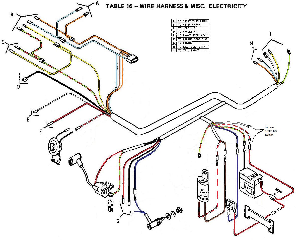
Lazer Wiring Actual
Lazer Wiring – battery
Lazer Sport 50 and General 5-Star have the same wiring, except for: 1) General has a steering lock key switch, that kills the spark and ungrounds the battery when the key is removed, 2) Lazer has an extra lt green/red ground wire, 3) Lazer battery is the smaller 6N2-2A, not 6N4B-2A.
These wirings are for the 1977 Lazer Sport 50, orange, top tank moped, made in Taiwan by Jui Li. They are not for the 2000’s Lazer 4-stroke mopeds, made in China by Bashan. That is a completely different “Lazer”.
Lazer Battery Versions: All Lazers use a 6N2-2A small 6 volt battery. Modern replacement batteries have different wires than the original batteries did. See section “B” about Battery Wires.
M=====================

Manet-Puch Korado
remake of ’86 Puch 1-sp
all lights 1 wire 12VAC
2-wire CDI magneto
Manet Wiring: This is a mid to late 1990’s Puch remake, made in Hungary by Manet. It is better known as the “Puch Korado”. Some things, like the engine, are the same as Puch, but the electrical and wiring is all different. Like all the other all-AC modern (1990’s and later) mopeds, the Korado has all the lights on one wire, with a 12VAC shunt-type voltage regulator. Like everything modern, it has a completely separate and independent CDI (capacitor discharge ignition) system that in no way depends on the lights. The CDI has no pulser coil.
Manet/Korado also made the mid-to-late-1990’s Jawa remake. The wiring for that not currently available, but is expected to be close to this wiring and electrical equipment.
Minarelli Wiring Diagram
for Testi/Gitane & others
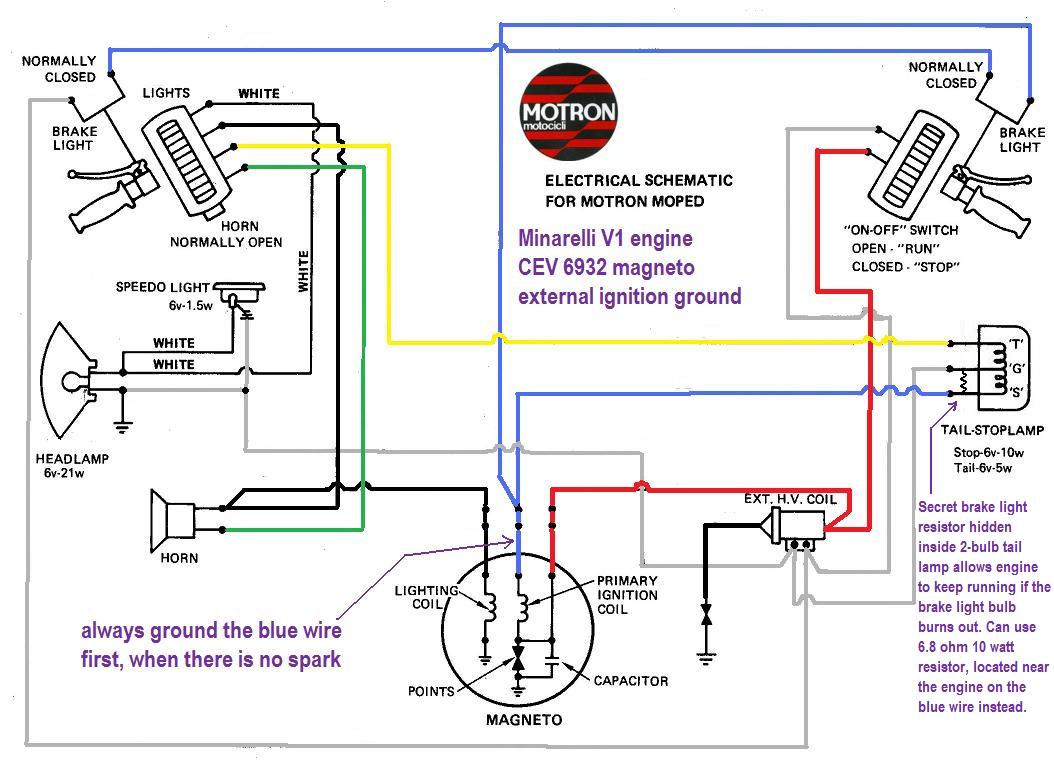
Minarelli Wiring: Most Italian mopeds, US models, that have Minarelli engines have this same wiring, functionally. Many have the same exact colors as well. There are at least 21 names: Aspes, Baretta, Bianchi, Cimatti, Concord, Fantic, Gadabout, Gitane, Intramotor, Lem, Maico, Motomarina, Motron, Pryer, Red Foxi, Safari, Silver Foxi, Snark, Testi, Yankee Peddler, and others. They all have the Minarelli V1 or V1L engine with CEV 6932 3-wire magneto with external ignition ground (blue wire) powering the brake light. Ground the blue wire first if there is no spark.
Morini Wiring Diagram
Morini Wiring: Franco Morini moped engines can have two possible Dansi magnetos. Which one it has is determined by a number stamped on the flywheel. Some Italian mopeds, US models, that have Morini engines have this same exact wiring. This “universal” wiring can be configured for either NC-in-series (for Dansi 101765 or 101732), or NO-in-parallel (for Dansi 101286 magneto) brake light switches. Most others wirings are functionally the same as one of these two versions. There are dozens of brand names: Arciero, Benvenuti, Bianchi, Colt, Cosmo, F. Morini (no relation to Franco Morini), Intramotor, Italjet, Italvelo, Italtelai, Lem, Malaguti, Motomarina, Motobecane, Negrini, Pacer, Snark, Velomec, West Wind, and others. Morini is only the engine name.
Dansi magneto 101286 3-wire 2-coil
has normally open brake light switches in parallel and an internal ignition ground.
Dansi magnetos 101765 and 101732 3-wire 3-coil
have normally closed brake light switches in series and an external ignition ground that powers the brake light.
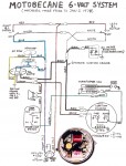
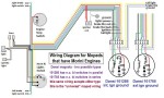
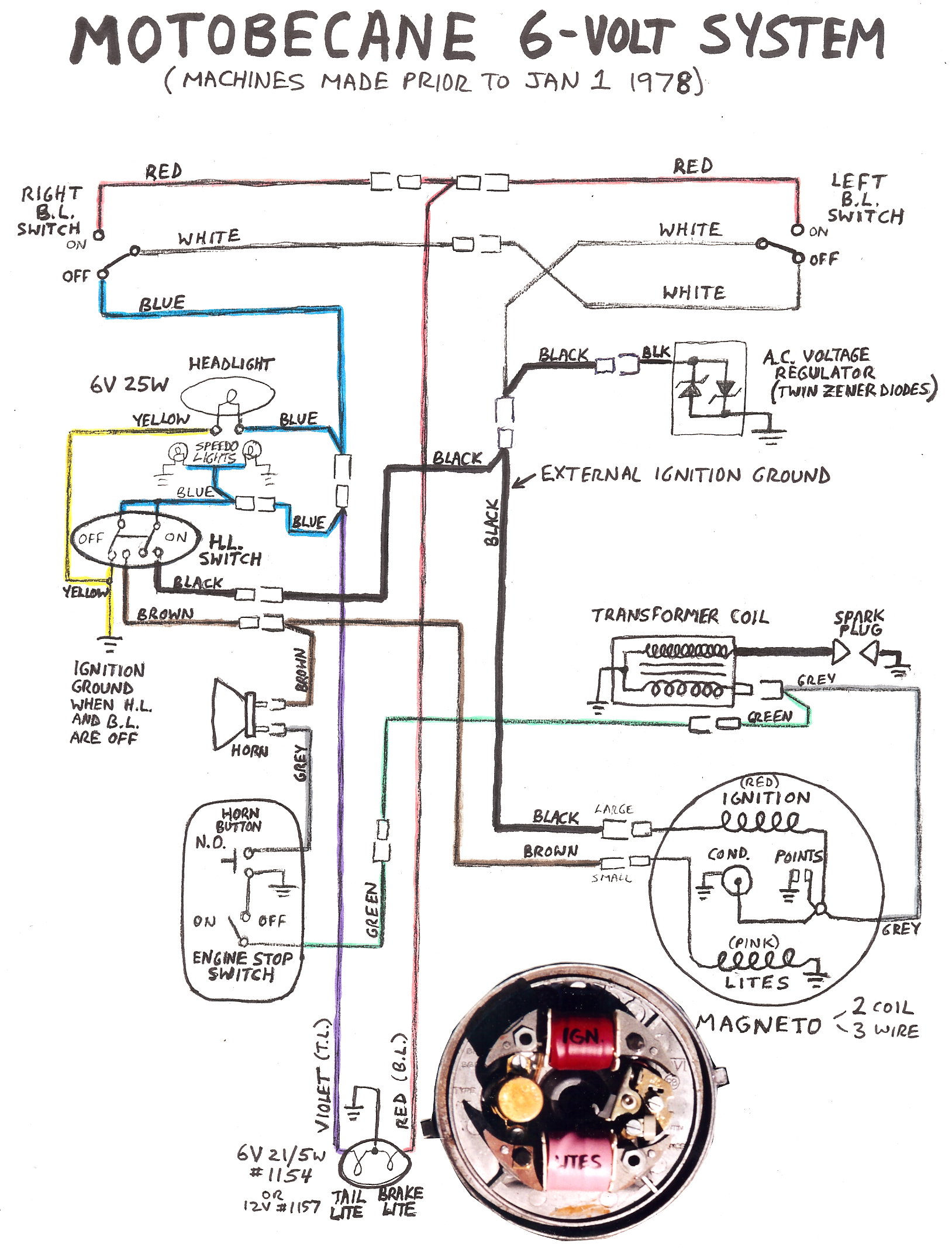
Motobecane 6V
1974-77 2-coil mag
3-wire Novi mag
external ign. gnd
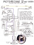
Motobecane 12V
1978-80 3 coil mag
3-wire Novi mag
internal ign. gnd
Motobecane Wiring: Two versions for USA model mopeds.
Early “6 volt” version: Before Jan 1978, Motobecane mopeds had a 2-coil Novi magneto, with an external ignition ground. The ignition assisted in keeping the lights bright, in a complex way.
Later “12 volt” version: After Jan 1978, Motobecane mopeds had a 3-coil Novi magneto, with an internal ignition ground. However, the ignition coil still needs at least one of the two neighboring lighting coils to be active. Amazingly, the lights not working can make it loose spark, even though they are not connected. It has to be from the magnetic field. The wiring is also complex.
Motobecane 6V 1968 Euro model
Euro version: They were much simpler. No brake light and less watts.
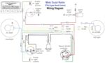
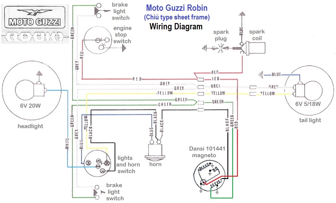
Moto Guzzi Robin (Chiù)
sheet frame, Benelli engine
Dansi 101441 magneto
internal ignition ground
Moto Guzzi Wiring: There are two kinds of Moto Guzzi Robin. They have the same name but different frames and wiring. Moto Guzzi made a stamped sheet-metal frame model, called Chiù in Europe, and Robin in the US. They also sold a Robin with a mono-tube frame made by Seimm. Both kinds had the 1970’s Motobi (Benelli) moped engine, with a Dansi 3-wire magneto.
Moto Guzzi Robin (mono-tube) The mono-tube Moto Guzzi Robin is identical to a Benelli G2. The Dansi 3-wire magneto had an external ignition ground on the green wire. It must always be connected to ground to have spark.
Moto Guzzi Robin (sheet frame) The sheet frame Moto Guzzi Robin is the US version of Chiù. The Dansi 101441 3-wire magneto had an internal ignition ground. It would never loose spark because of loose brake light wires, but the lights are not as bright.

Motobecane Sebring
Morini MO1 or MO2 eng.
Dansi 101286 magneto
external ignition ground

Motron Wiring Diagram
Minarelli V1 engine
CEV 3-wire magneto
external ignition ground
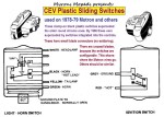
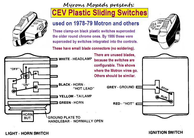
Motron Sliding Switches
left,CEV 8188 lites & horn
rt, CEV 8189 engine stop
Motron Wiring: Functionally the same as the “Minarelli Wiring”. 1978-79 had the CEV clamp-on plastic slide switches. 1980-81 had the CEV “diamond” switches integrated (fitted into) the Domino controls.
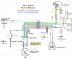
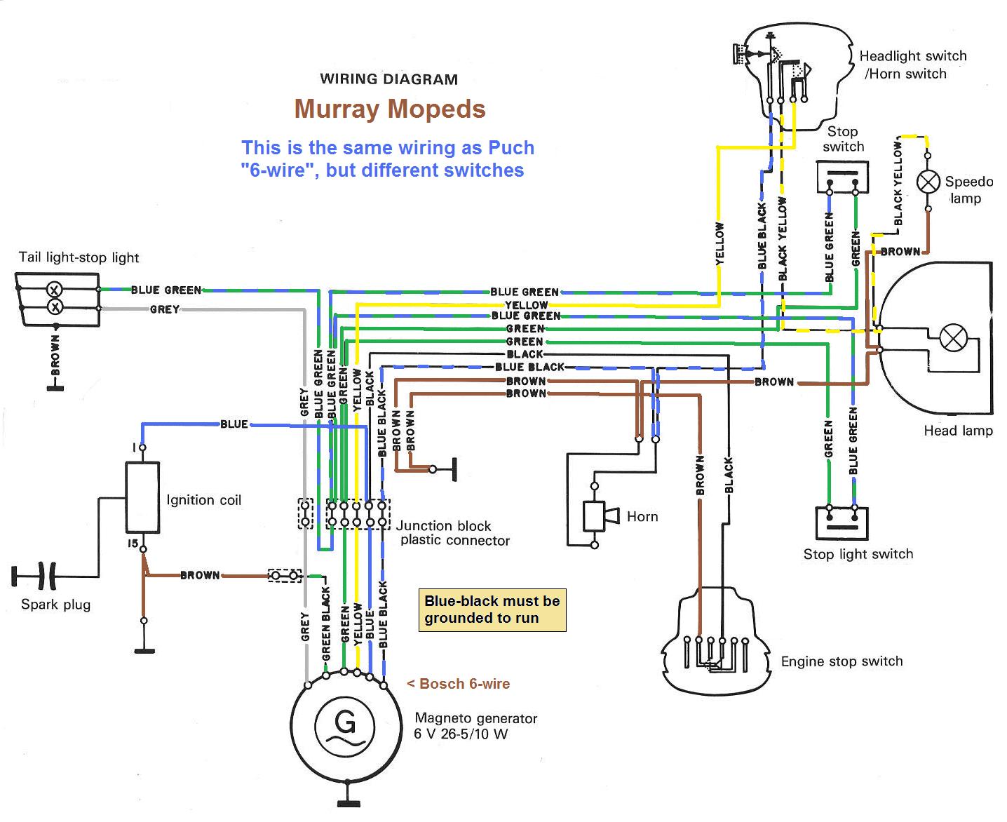
Murray Wiring Diagram
Bosch 6-wire magneto
external ignition ground
Murray Wiring: Same as Puch Series B. Bosch 6-wire with external ignition ground powering the horn. Ignition, brake light, tail light, and head light all have separate source coils (armatures). Ground the blue/black wire first if there is no spark.
N=====================
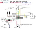
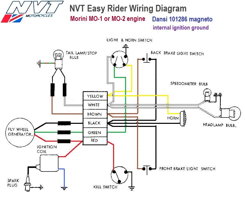
NVT Easy Rider ER1,ER2
Morini MO1 or MO2 eng
Dansi 101286 magneto
internal ignition ground
Negrini Wiring: The wiring diagram is not in the owners manual by MMI. See Morini Wiring. What number is on the magneto flywheel determines one of two possible wiring schemes. See Morini Wiring and Dansi Magnetos.
NVT Wiring: NVT (Norton Villiers Triumph) mopeds and motorcycles are made in England. The Easy Rider ER1 and ER2 mopeds all use the Dansi 101286 magneto, according to the owners manual wiring. On that magneto/generator, the lighting coil is split into two concentric coils, one for brake light and horn (black wire), and one for head light, tail light, and speedo light (green wire). The other coil is ignition (red wire), with an internal ground, so it is isolated from the lights.
O=====================
Odyssey Wiring: Odyssey mopeds and engines are made in Germany by Solo. They have German style wiring with separate generator wires for each light. Euro models have a Bosch 0212 005 011 80mm clockwise magneto. USA models have a Bosch 0212 124 039 90mm clockwise magneto. More to follow…
P=====================
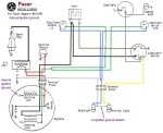
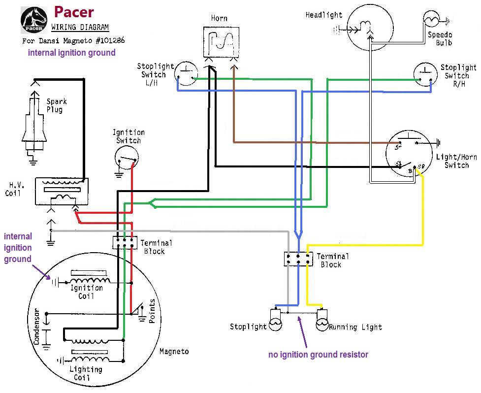
Pacer Wiring Diagram
for Dansi mag 101286
internal ignition ground

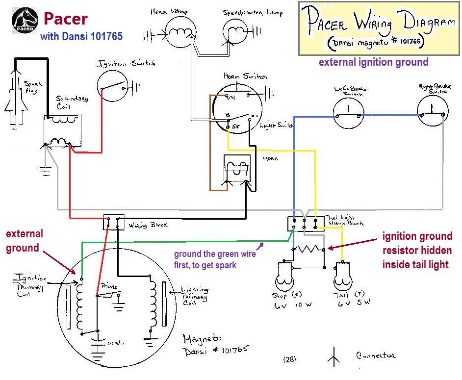
Pacer Wiring Diagram
for Dansi mag 101765
external ignition ground
Pacer Wiring: Pacer is an Italian moped with either a Morini MO1, MO2, or M1 engine. Early models with frame number 15499 and below, all have the Dansi 101286 3-wire 3-coil magneto, with the ignition source coil grounded internally. Later models with frame number 15500 and above can have either 101286 or the Dansi 101765 3-wire 2-coil magneto. The only way to tell is by the number stamped on the flywheel. The brake light switches, wiring harness, and tail light are different for each magneto type. See also Morini Wiring.
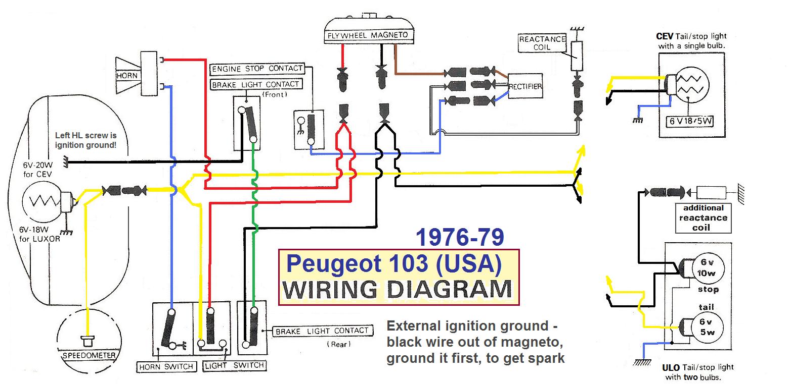
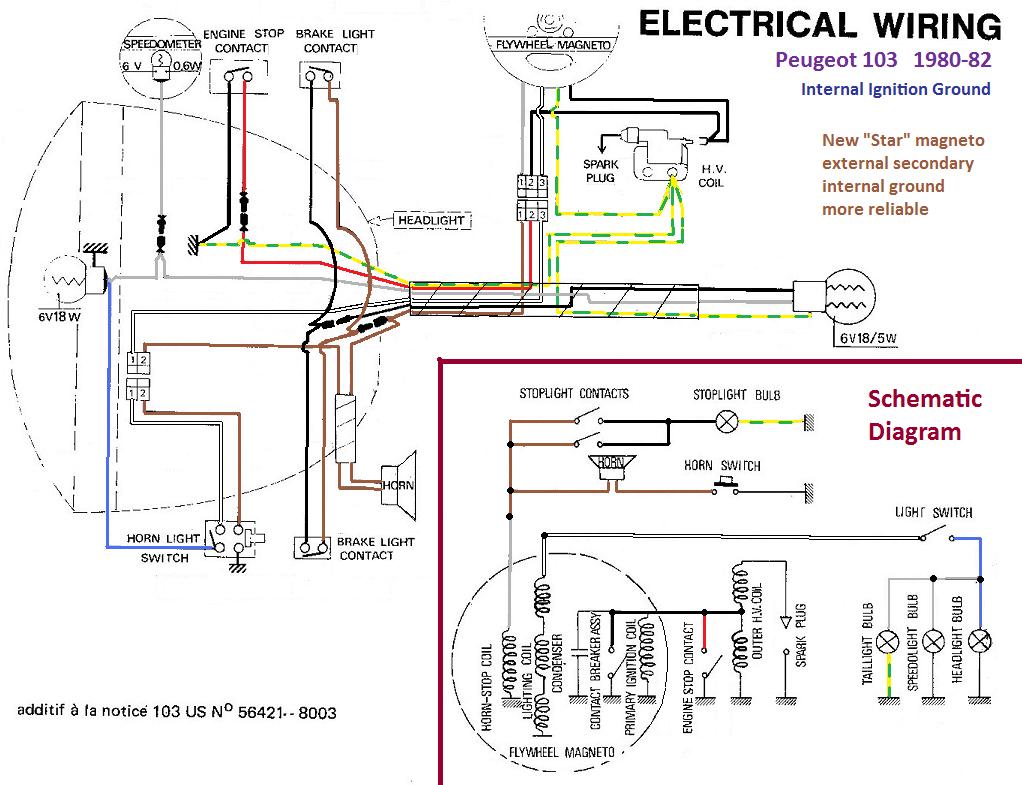
Peugeot Wiring: Peugeot was one of 3 or 4 moped makers that made their own magneto. The French maker chose to be different and make their flywheel have puller threads M20x1.0, instead of the Germans M22x1.5 or Italians M19x1.0. Pre-1980 Peugeots have an external ignition ground running the brake light. Remove the tail light assembly or unplug the wires and it won’t run. Ground the black wire under the engine by attaching it somewhere to ground (such as the tail of the decomp cable wire), to get spark, when there is no spark. 1980 and later Peugeots do not have that problem, because they have an internal ignition ground. Their ignition does not rely on any of the lights.

Peugeot 103 1976-79
103 LS, 103 LVS, 103 SP
3-wire + spark magneto
internal transformer with
external ignition ground
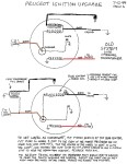
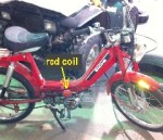
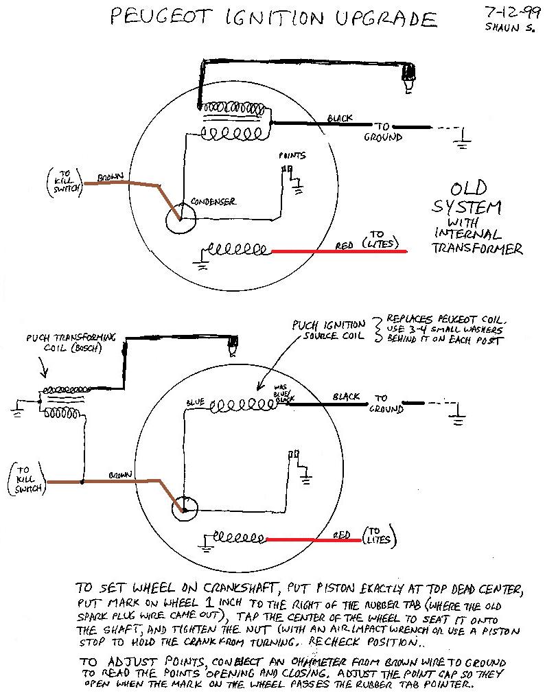
Peug Ign Upgrade:
int to ext trans. coil
Peugeot Ignition Upgrade: Way back in the mid 1980’s, Peugeot 103 mopeds, 1976-1979 began to burn up condensers and points rapidly. Some of the coils would send voltage spikes. In the late 1980’s the supply of coils and stators had pretty much been used up. By 1990, even brand new Peugeot coils would not work good for long. They were going bad just sitting on the shelf. Out of desperation Shaun found a substitute inner source coil, from a Puch. It fits the Peugeot coil bolts, if they are bent in a little. A Puch outer coil (transformer) was added onto the right frame near the carburetor. ’78-79 and some ’77 103’s already have the external coil mount. 1977-earlier has to be welded on. There is a whole chapter about that here.
These 1980 and later Peugeot models already have the upgraded ignition, with external transformer coil.
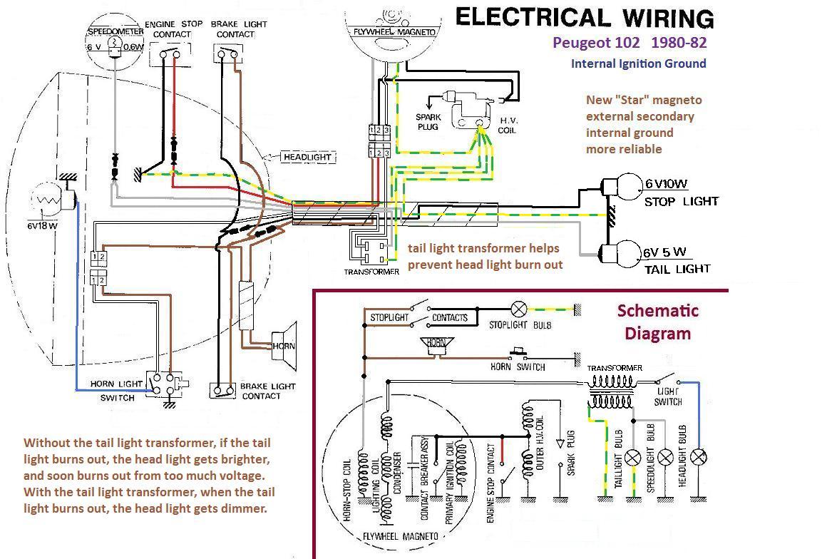
Peugeot 102,103 1980-on
new “star” magneto
internal ignition ground
Peugeot 103 1980-83
103 LS,LVS,SP,SPB, TSM
3-wire “star” magneto
internal ignition ground
Peugeot 102 1980-83
w/tail light transformer
3-wire “star” magneto
internal ignition ground
Piaggio Wiring: Vespa is one brand of the parent company Piaggio. For 1970’s Vespa mopeds, there many wiring diagrams with photos and service info, located in a separate Service section, under Vespa Electrical https://www.myronsmopeds.com/category/vespa-electrical/
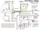
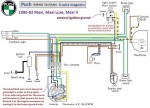
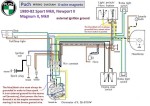
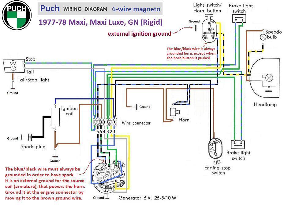
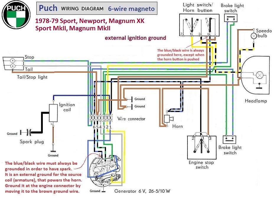
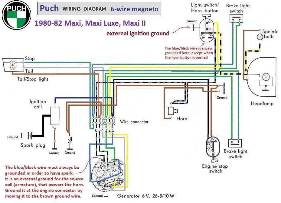
Puch Wiring: All 1978-1986 Puch mopeds, USA models, have a 6-wire Bosch magneto, with points, and with an external ignition ground that powers the horn. Unplugging one of the horn wires, then pressing the horn button stops the engine. In addition to that, loosen the horn/light switch clamp from the handlebar, and a brand new Puch will not run, because of disconnected horn wires. Really! Puch is the only maker that chose to meet the USA standards that way. Almost everyone else chose to power the brake light with the ignition ground. Maybe the others figured if you’re already using the brakes and your engine dies, it’s not as bad.
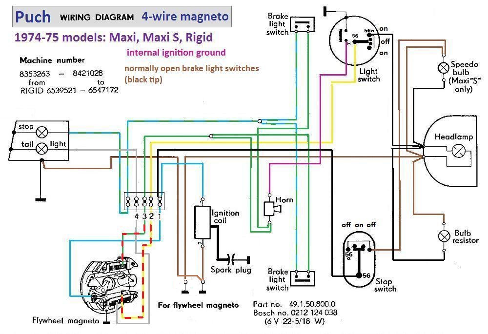
Puch 1974-75 (4-wire)
Maxi, Maxi-S, Rigid (GN)
Maxi 8353263-8421028
Rigid 6539521-6547172
4-wire Bosch magneto
1-speed 0212 124 038
internal ignition ground

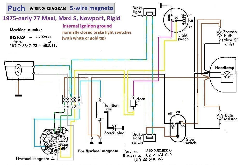
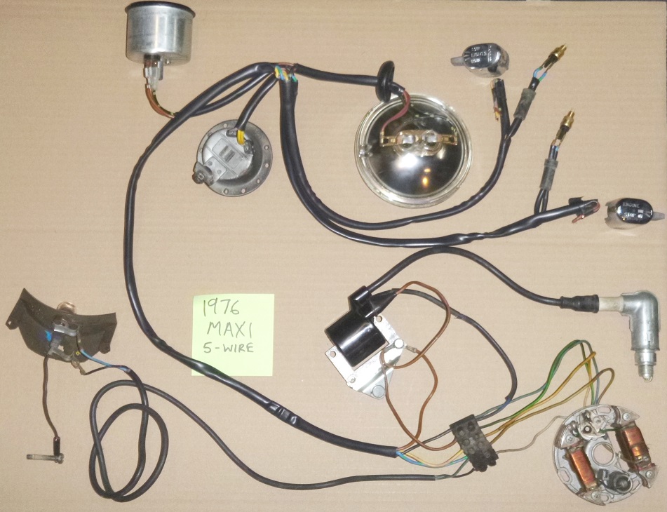
Puch 1976-77 (5-wire)
Maxi-N, Maxi-S, Nostalgic
Maxi 8421029-8709891
Rigid 6547173-6830115
5-wire Bosch magneto
1-speed 0212 124 042
internal ignition ground
Puch 1976-77 (5-wire)
Maxi-N, Maxi-S, Nostalgic
actual wiring laid out
ULO 2-bulb tail light
Merit chrome switches

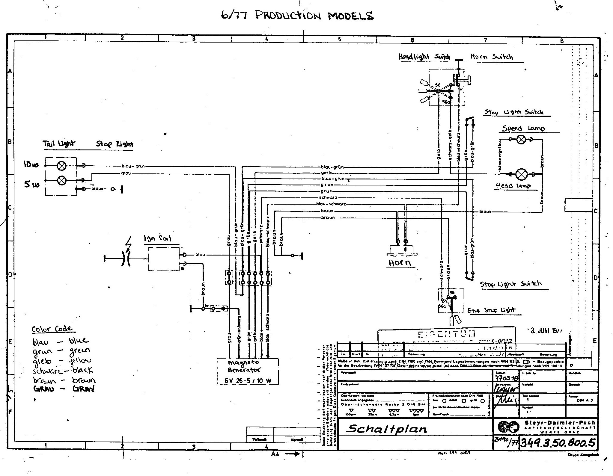
Puch Schaltplan Jun-77
The original 6-wire plans,
for US models, where the
ignition powers the horn.
external ignition ground
Puch 1977-78 (6-wire)
Maxi, Maxi Luxe, Rigid
Maxi 8709892-???????
Rigid 6830116-???????
6-wire Bosch magneto
1-speed 0212 124 043
external ignition ground
Puch 1978-79 (6-wire)
Maxi, Maxi II, Luxe, Rigid
6-wire Bosch magneto
1-speed 0212 124 043
2-speed 0212 124 044
external ignition ground

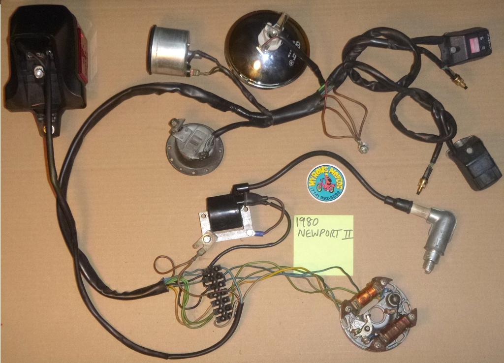
Puch 1978-79 (6-wire)
Sport, Newport, Magnum
Sport MkII, Magnum MkII
1-speed 0212 124 043
2-speed 0212 124 044
external ignition ground
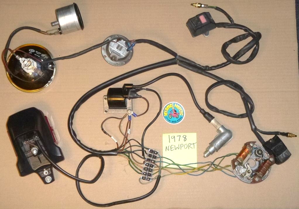
Puch 1978-79 (6-wire)
Sport, Newport, Magnum
Sport MkII, Magnum MkII
w/square black switches
CEV 2-bulb tail light
external ignition ground
Puch 1980-82 (6-wire)
Maxi, Maxi II, Maxi Luxe
1-speed 0215 254 658
2-speed 0215 254 674
external ignition ground
Puch 1980-82 (6-wire)
Sport MkII, Newport II,
Magnum II, MkII
2-speed 0215 254 674
external ignition ground

Puch 1980-82 (6-wire)
Sport MkII, Newport II
Magnum II, MkII
w/square black switches
external ignition ground
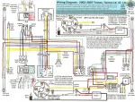
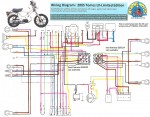
Puch 1980-82 (6-wire)
Magnum MkII, Limited Ed
with ignition key switch
2-speed 0215 254 674
external ignition ground

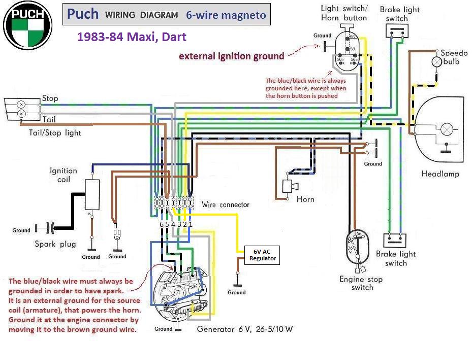
Puch 1983-84 (6-wire)
Maxi, Dart with
6VAC voltage regulator
1-speed 0215 254 658
external ignition ground
Puch 1983-84 (6-wire)
Maxi, Dart with
6VAC voltage regulator
original b & w diagram
external ignition ground

Puch 1983-84 (6-wire)
Dart (shown), Maxi
Merit chrome switches
external ignition ground
Puch 1984-86 (6-wire)
Maxi Sport LS, MS LS II
Cobra, Cobra II, ’85 Maxi
w/square black switches
external ignition ground
Puch Korado Wiring
1995 made by Manet
CDI 2-wire magneto
(internal ignition ground)
Puch Re-makes: After the last Austrian made Puch in 1986, three companies have reproduced the 1980’s Puch mopeds. Piaggio (Italy, early 90’s), Hero (India, late 90’s), and Manet (Hungary, late 90’s). While the most of engine is the same, the electrical equipment and wiring is different, more modern. All 1990’s and later mopeds have CDI ignitions with an internal ignition ground. Thanks to the advent of electronic solid state voltage regulation in the mid 1980’s, allowing stronger magneto/generators (50 or 80 watts instead of 30) without bulb burnout, modern mopeds don’t need to borrow “juice” from the ignition, so their ignition is separate from the lights or horn, and thus way more reliable.
Q=====================
R=====================
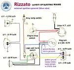
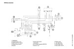
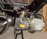
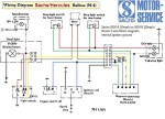
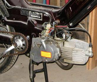
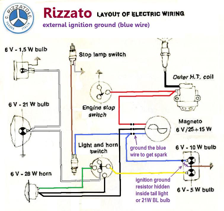
Rizzato Califfo Wiring
CEV 3-wire magneto
external ignition ground
Rizzato Wiring: Italian made Rizzato has it’s own engine, with either a CEV 6952 or a Dansi 3-wire magneto. Rizzato Califfo uses the same wiring and wire colors as Italian-made mopeds with Minarelli engines. Red is ignition, black is lights, and blue (for CEV) or green (for Dansi) is an external ignition ground, powering the brake light. Unpluging the brake light wires on a Rizzato will make it stop running. When it has no spark, always ground the blue wire first. Outside wiring disconnected is often the cause.
S=====================
Sachs/Hercules Wiring: Sachs mopeds, made by Nürnberger Hercules Werke GMBH, should not be confused with mopeds that have Sachs engines, like General, Grycner, Clinton, Colombia, AMS, Foxi, Sparta, Flying  Dutchman, Eagle, and many others. Most of the “true” Sachs mopeds can be identified by the Hercules “H” logo stamped into the headlight mounts. Sachs early models, roughly 1976-1978, had an internal ignition ground. Those never lost spark because of bad brake light wires. Sachs later models, roughly 1978-1981, had an external ground. Those had a secret ignition ground resistor hidden inside the CEV 2-bulb tail light. If that went bad, the ignition would not have spark when either brake was applied (or all the time, if the brake light switch wires were loose). In that case attach the ignition ground wire, that comes out of the engine, to ground. It’s blue/black for Bosch magnetos, and black for Motoplat magnetos. That will restore the spark, but disable the brake light, for emergency use or troubleshooting.
Sachs/Hercules Wiring for Hercules-made mopeds with Sachs 505 engines (pedals inside engine):
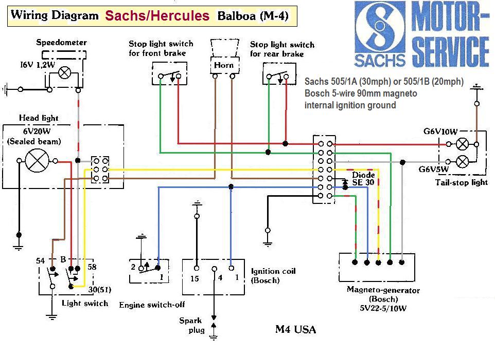
Sachs Balboa M-4 (USA)
Sachs 505/1A or 1B eng
Bosch 90mm 5-wire mag
internal ignition ground
ULO 2-bulb tail light
Sachs 1980 Suburban
wires inside head light.
Behold, the “mystery”
diode that powers the
horn from the ignition.

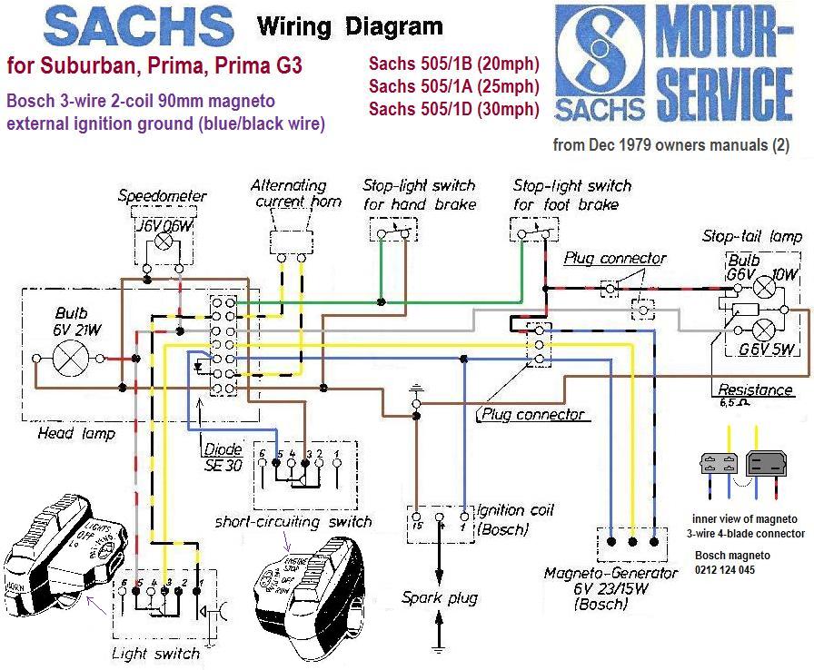
Sachs Suburban,Prima,G3
Sachs 505/1D, 1A, 1B
Bosch 3-wire 90mm mag
external ignition ground
Sachs Suburban 1978-on
shows magneto wires plug
505/1D with Bosch 3-wire
external ignition ground
CEV 2-bulb tail lite w/res
Sachs/Hercules Wiring for Hercules-made mopeds with Sachs 504 engines (pedals outside engine):

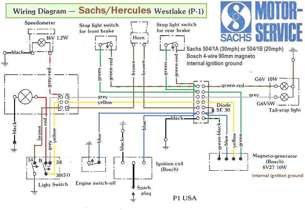
Sachs Westlake P-1 (USA)
made by Nürnberger
Hercules Werke GMBH
Sachs 504/1A or 1B eng
Bosch 4-wire 80mm mag
internal ignition ground
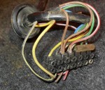
Sachs 1978 Westlake P-1
504/1A w/Bosch 4-wire
internal ignition ground
identified by black coil
ULO 2-bulb tail lite
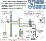
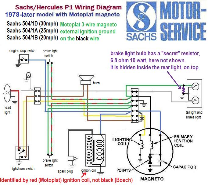
Sachs/Hercules 1978-on
Westlake,Sundancer (P-1)
Sachs 504/1D,1A,1B
Motoplat 3-wire magneto
external ignition ground
Sachs 1978 Westlake P-1
504/1D Motoplat 3-wire
external ignition ground
identified by red ign coil
CEV 2-bulb tail lite w/res
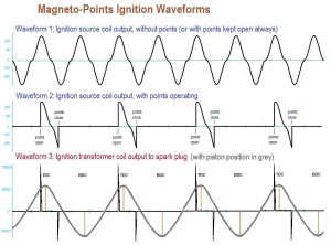
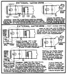
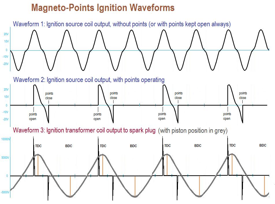
Ignition Waveforms: Interrupted AC
Curve 2 shows how the points interrupt the source,
and cause the unused negative triangular sections.
On a Hercules, they get less when the horn is used.
On all other bikes those minus voltages are unused.
“Mystery” Diode: All Hercules-made mopeds borrow electric power from the ignition wire (not the ignition ground) to power the horn. Normally this would kill the spark. But the wise Germans found some unused power. It’s a little hard to understand, without lots of pictures and hand waving. The flywheel has four bar magnets aligned N to N and S to S, so there are two Norths and two Souths per revolution. The current generated reverses direction every 90 degrees. The points open (the spark moment) near one of the magnetic maximums, say North. About 45 degrees later, the field is zero, and heading South. The points stay open for about 20 or 40 more degrees. That’s when there’s a short period of available reverse current/power. (When the points finally close, a secondary weaker spark occurs, with reverse polarity, but has no effect on the already burned gas.) The diode allows that reverse current to flow to the horn instead of to the spark coil, so no secondary reverse spark is produced at the spark plug when the horn is on. The diode one-way-gate stops the forward current from flowing out to the horn, so the main spark is not affected. The main spark only needs the forward current and not the reverse.
Always disconnect the power diode, aka “Mystery Diode”, and the engine stop switch, when troubleshooting for no spark, on a Hercules-made moped. It’s either inside the head light, or down near the engine. It is for making the horn not dim the headlight.
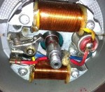
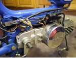
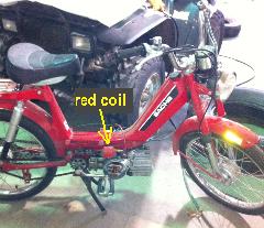
Sachs ’78 P-1 with 504/1D
Motoplat 3-wire magneto
top: ignition – blue, black
bottom: lites coil – yellow
Motoplat (made in Spain) 80mm magneto/flywheels used on some Hercules, Sparta, and KTM mopeds with Sachs 504 engines are gold colored, and have the number 9600089. The wires are yellow = lights, blue = ignition, black = ignition ground. Their points have a built-in red wire. Condenser is CEV-compatible.
Motoplat 80mm flywheels used on 1976-86 Derbi mopeds have the number 9600099. Those wires are red = lights, green = ignition, blue = ignition ground. Their points are different, and also have no built-in wire. Condenser is CEV-compatible.
Sears Free Spirit Wiring
Puch 1977-78 (6-wire)
external ignition ground
Sears Free Spirit Wiring: The Free Spirit moped, made by Kromag, has the same wiring and electrical equipment as 1977-78 Puch Maxi (6-wire). In fact, the whole bike is Puch, but it doesn’t say “Puch” anywhere on it. All of the brand markings have been removed, to make it seem like Sears made it. Like all the Bosch 6-wire magneto Puch wirings, the blue/black wire that powers the horn is an external ignition ground for the source coil. Unplug the horn wires and loosen the light/horn switch clamp from the handlebar, and a Free Spirit will loose spark and not run. Also, like 78-later Puch, the horn button does the opposite of all other horn buttons in the world. It is normally closed, and when you push, it is momentarily open. If you replace it with any other horn button, the horn would be on all the time, and go off when you push the button. To eliminate the chance of loosing spark due to bad horn wires, simply gound the blue/black magneto wire at the terminal strip above the engine, by moving it over to the brown wire that goes to ground.
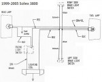
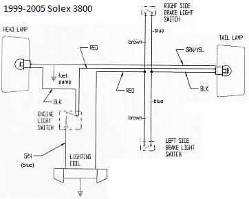
Solex 3800 Wiring
1973-74 S 3800 USA
1-wire + spark magneto
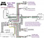
Solex 4600 (USA) Wiring
3-wire + spark magneto
Solex 3800 Impex
Lights Wiring only
points or CDI magneto
Solex Wiring: The 1970’s and earlier Solex 3800 had only one wire outside of the engine, going to the tail light. Instead of wires, the head light and switch had direct contacts. The ignition spark coil was internal, with the spark plug wire coming out of the magneto.
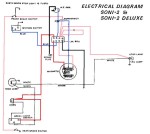
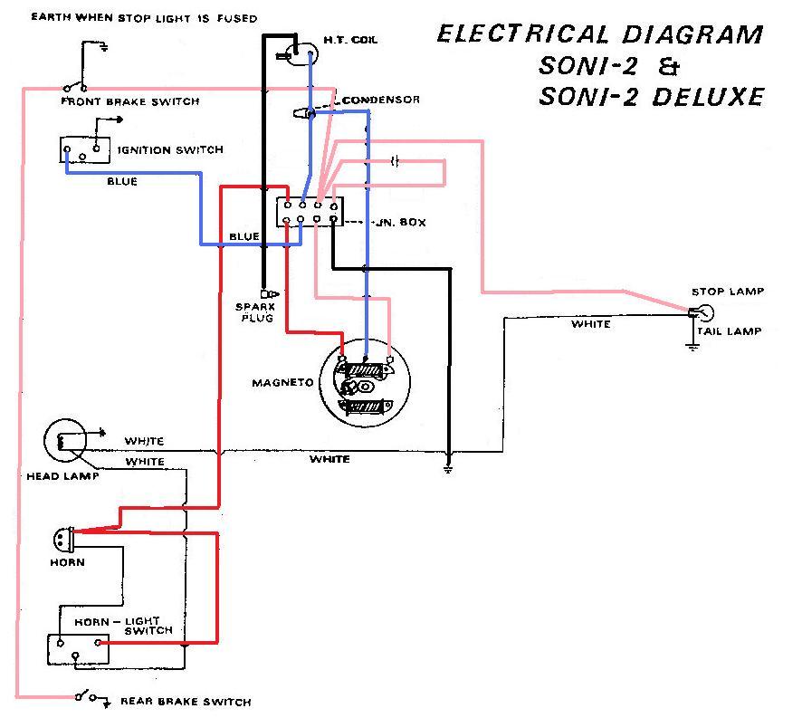
Soni 2 Wiring Diagram
India made Vespa Ciao
3-wire points magneto
external ignition ground
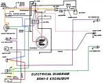
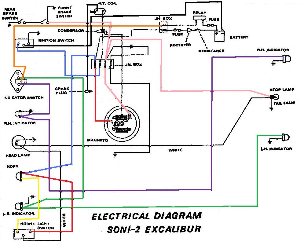
Soni 2 Excalibur Wiring
turn signal model
India made Vespa Ciao
3-wire points magneto
external ignition ground
Soni Wiring: This 1980’s India remake of a 1970’s Italian made Vespa/Piaggio moped, has functionally the same wiring, pretty much, as Vespa did. Unlike the Kinetic, a 1990’s India made Vespa remake, that has a CDI ignition, the Soni has points, and an external ignition ground magneto that powers the brake light, like Vespa/Piaggio. When we say “ground the pink wire to get spark if the brake light filament burns out”, in India they say “earth when stop light is fused”. It looks like it has an emergency wire that would allow it to run if it lost spark from a blown brake light bulb or loose wire.
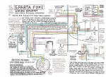
Sparta Foxi, early F.D.
with many notes added
ULO 2-bulb early taillight
Bosch 4-wire magneto
internal ignition ground
Sparta (with Bosch)
’76-78 Foxi, F.D, Sparta
ULO 2-bulb early taillight
Bosch 4-wire magneto
internal ignition ground
Sparta (with Motoplat)
’78-81 Dutchman, Sparta
ULO 2-bulb taillight w/res
Motoplat 3-wire 9800089
external ignition ground
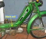
Sparta Wiring: Sparta had two 80mm magneto versions for the Sachs 504 engine, Bosch 4-wire and Motoplat 3-wire. The wires on the bike are the same, except Motoplat version has an external ignition ground, a tail light secret resistor, brake switch type NC not NO, and the brake switches wired in series, not parallel. The Motoplat version needs the brake light wires and correct bulb to have spark.
One way to tell which (brake light) wiring and magneto version a Sparta has, from a distance, is by the color of the ignition coil and plug wire. Motoplat is red, while Bosch is black. It’s the same situation as Hercules/Sachs wiring. Spartas with red coils have normally closed (white or brass tip) brake light switches in series, and a secret brake light resistor-diode circuit board inside the tail light. Spartas with black coils have normally open (black tip) brake light switches in parallel, and no brake light resistor inside the tail light.
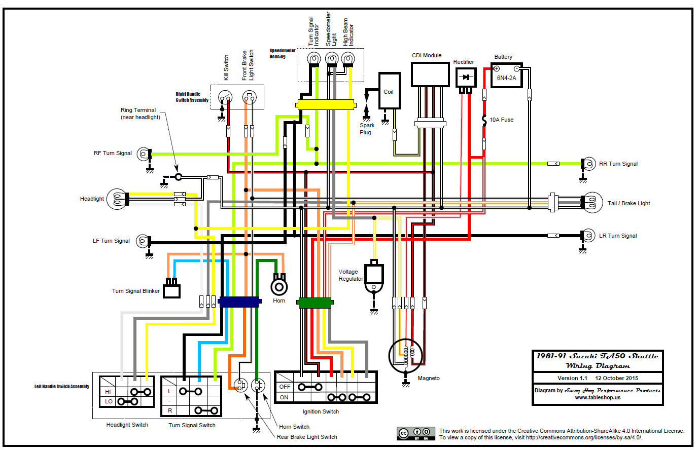
Suzuki Wiring: The early 1980’s Suzuki FZ50 (3.00 x 12″ tires) and FA50 (2.25 x 14″ tires) have pretty much the same engine, controls, wiring, and electrical equipment.
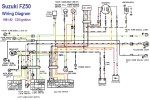
Suzuki FZ50 1981-82
5-wire CDI magneto
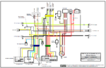
Suzuki FA50 1981-91
5-wire CDI magneto
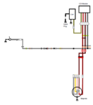
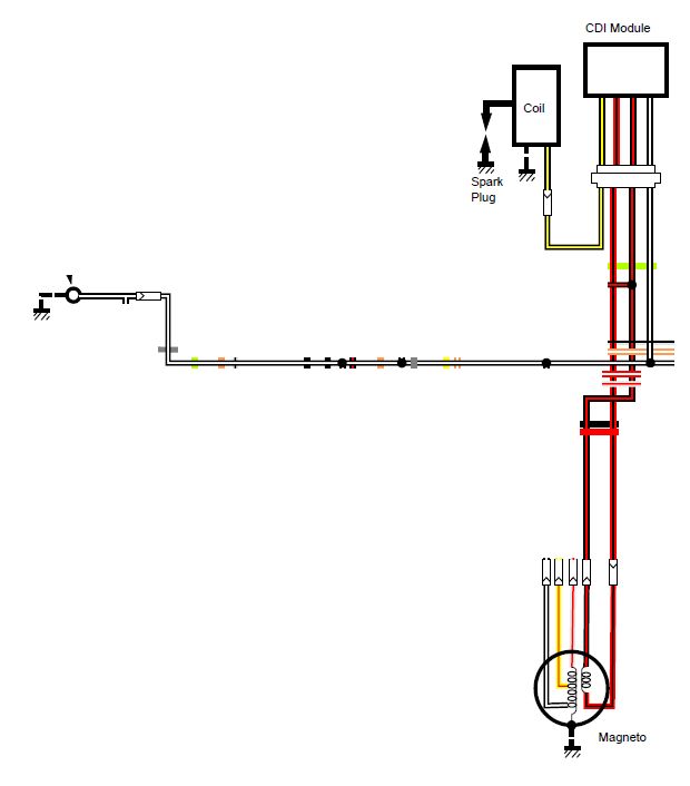
Suzuki FA50 wires needed to have spark
T=====================
Testi Wiring: Testi makes Gitane, Red Foxi, and other makes with Minarelli V1 engines. See Minarelli Wiring.
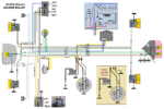
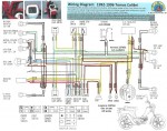
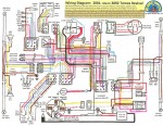
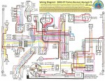
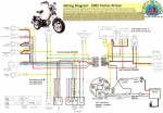
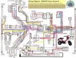
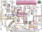
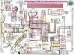
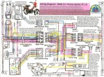
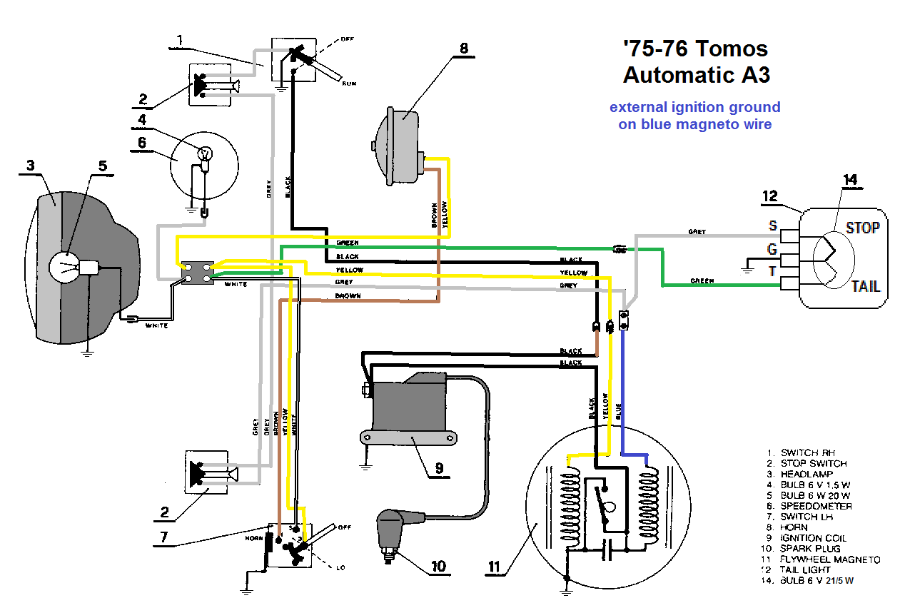
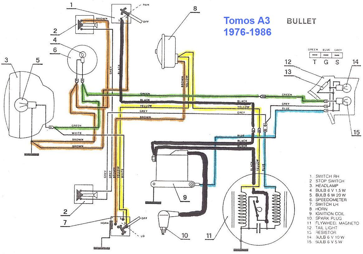
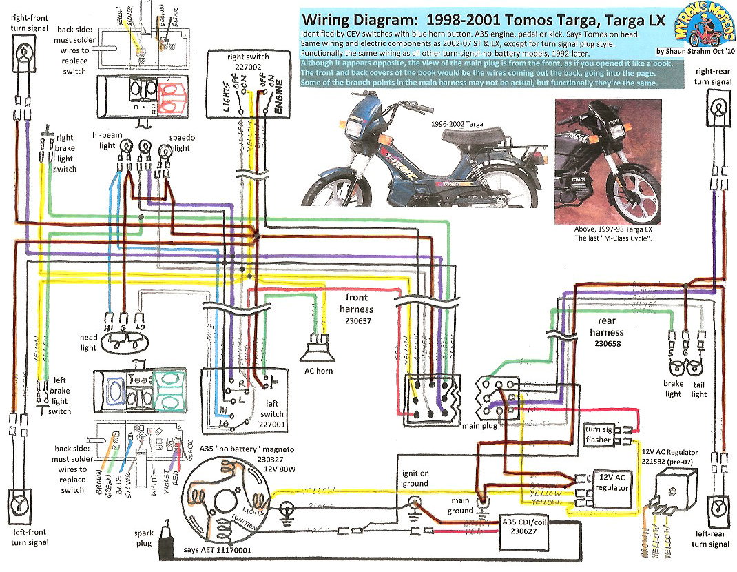
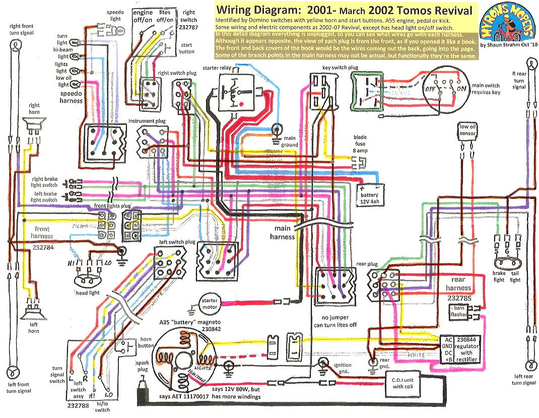
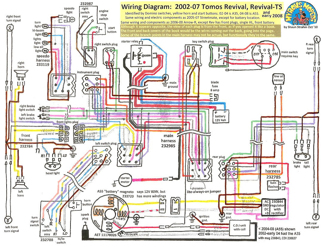
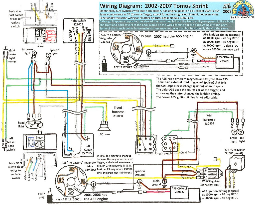
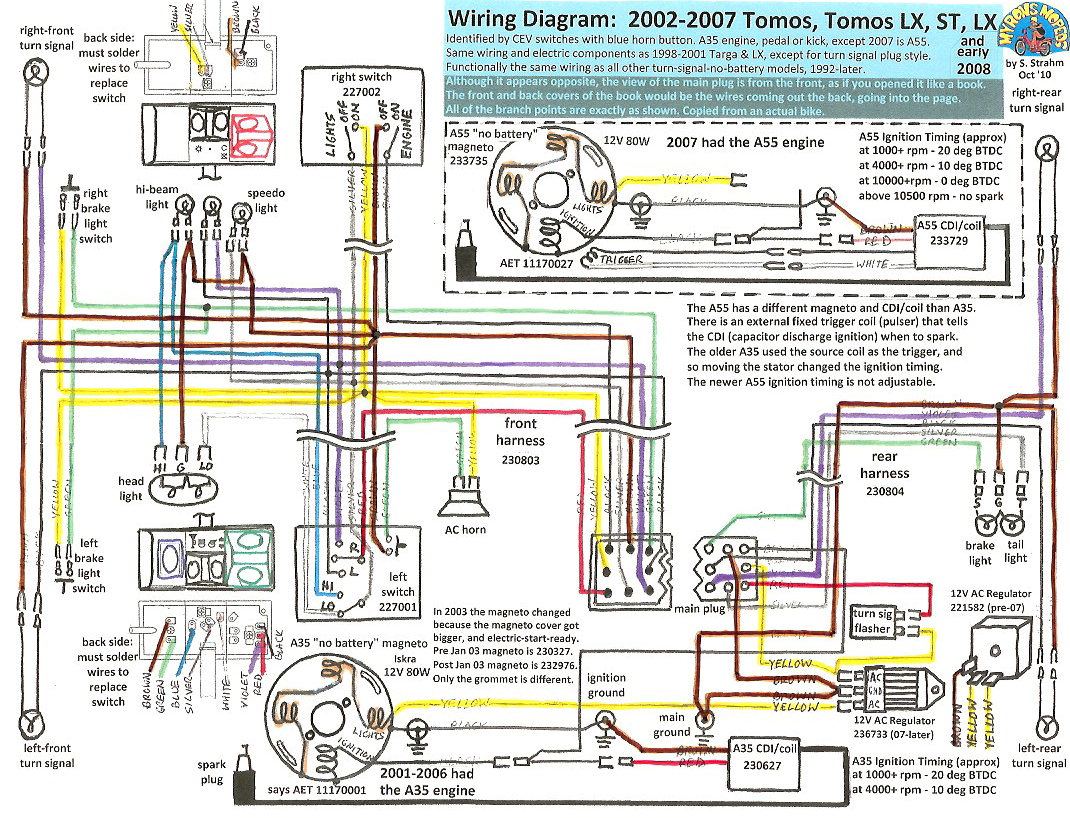
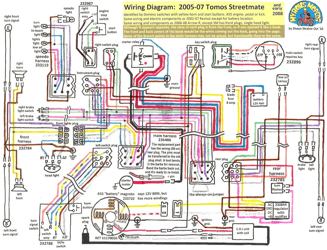
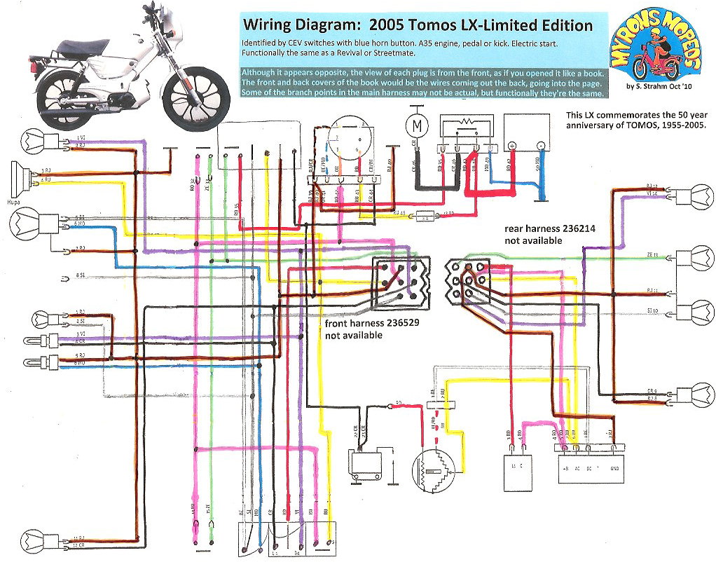
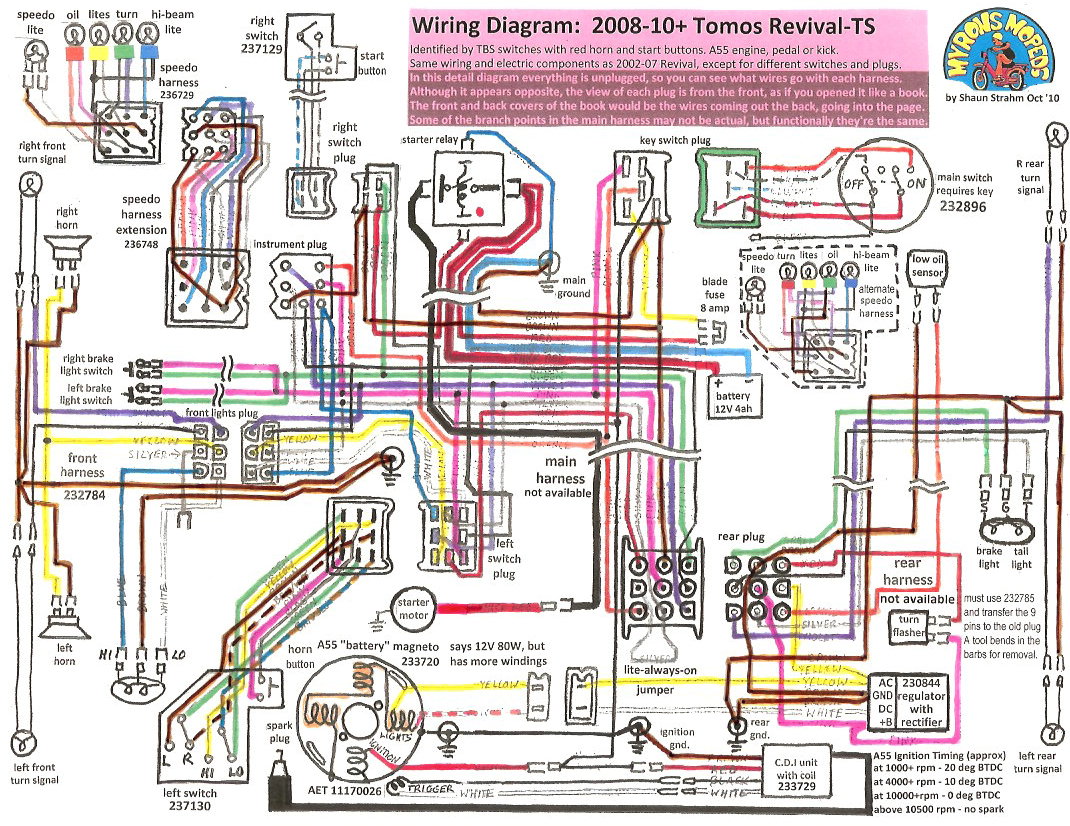
Tomos Wiring: Here is a complete, detailed, and accurate set of wiring diagrams. These took 200 hours, over a 3-month period, to gather, interpret, colorize, and edit for clarity. Many of the originals were terribly inadequate, although functionally correct.
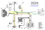
Tomos Automatic 75-76
3-wire mag, ext. ign gnd
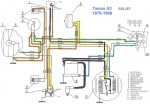
Tomos A3 Bullet 77-86
3-wire mag, ext. ign gnd

Tomos A3 Bullet 86-91
2-wire mag w/regulator
internal ignition ground
for improved reliability
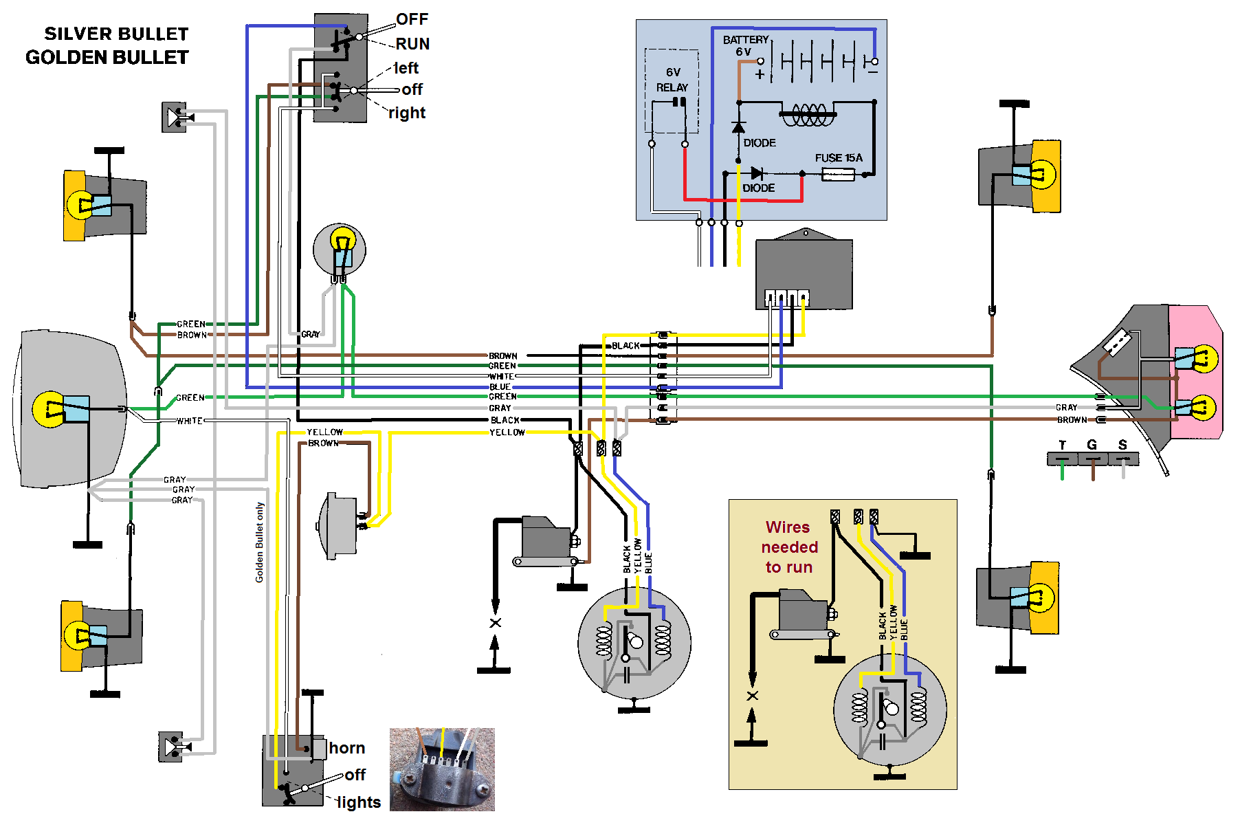
Tomos A3 Silver Bullet
early Golden Bullet 85-86
3-wire mag, ext. ign. gnd.

Tomos A3 Golden Bullet
& Golden Bullet TTLX
1986-91 int. ign. gnd.

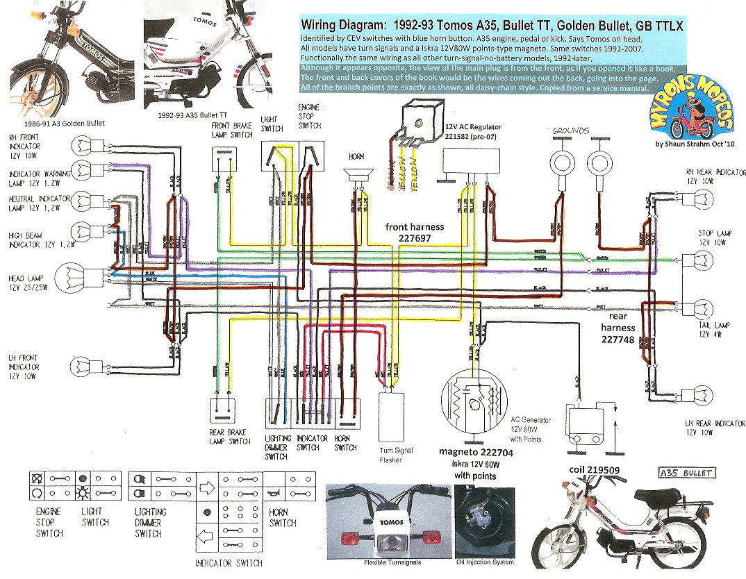
Tomos A35 Bullet 92-93
Iskra 2-wire magneto
internal ignition ground
Tomos A35 Colibri 92-96
Iskra 2-wire magneto
internal ignition ground
Tomos Sprint 1993-97
four different magnetos
internal ignition ground
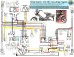
Tomos Targa 1994-95
Tomos Targa LX 94-95
four different magnetos
Tomos Targa 1996-97
Tomos Targa LX 96-97
Iskra 2-wire CDI magneto
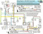
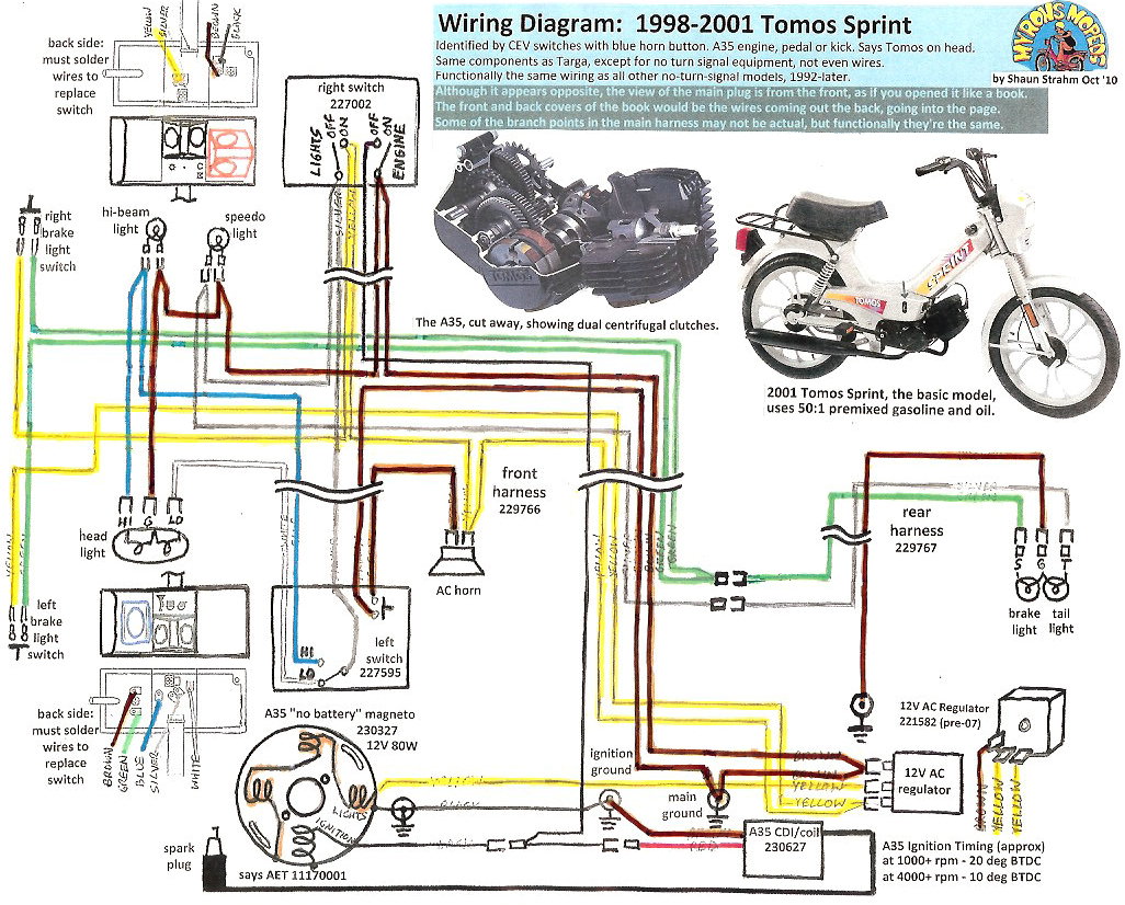
Tomos Sprint 1998-01
Iskra 2-wire CDI magneto
Tomos Targa 1998-01
Tomos Targa LX 98-01
Tomos Revival 2001-02
Iskra 3-wire CDI magneto
Tomos Revival 2002-07
Iskra 3-wire CDI mag A35
Iskra 5-wire CDI mag A55
Tomos Sprint 2002-07
Iskra 2-wire CDI mag A35
Tomos Tomos 2002-05
Tomos ST 2005-2007
Tomos LX 2002-2007
Tomos Streetmate 05-07
Iskra 5-wire CDI mag A55
Tomos Arrow 2005
Iskra 4-wire CDI mag A55
Tomos LX Limited Ed. 05
Iskra 3-wire CDI mag A35
Tomos Arrow-R 2006-08
Iskra 5-wire CDI mag A55
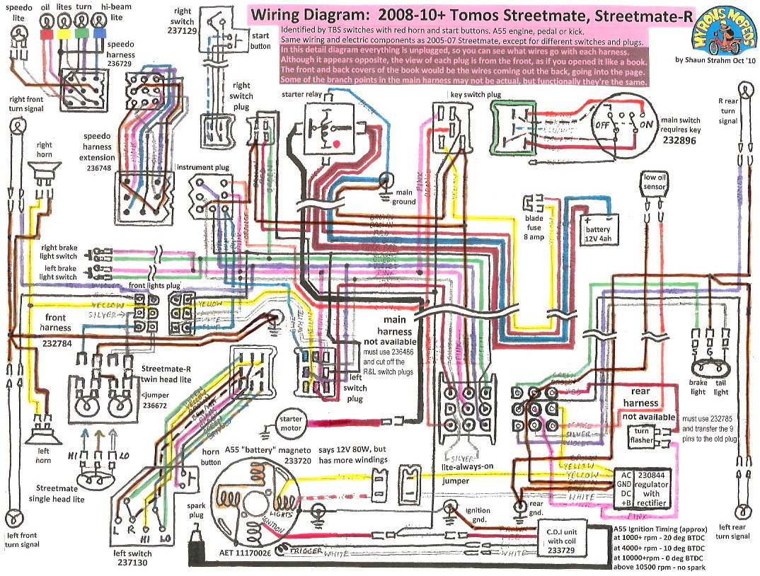
Tomos Revival 2008-12+
Kinetic 5-wire CDI mag
Tomos Streetmate 08-12
Tomos Str.mate-R 08-13
Kinetic 5-wire CDI mag
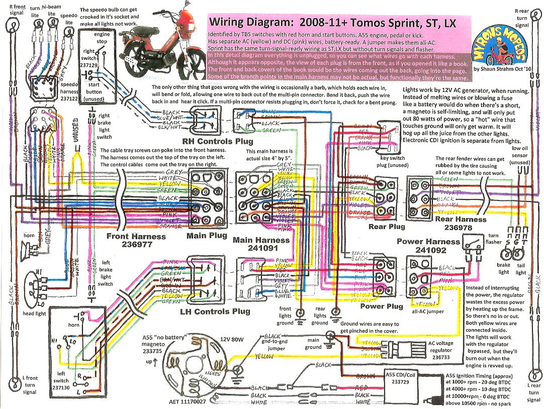
Tomos Sprint 2008-13
Tomos ST,LX 2008-2013
Kinetic 5-wire CDI mag
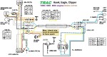
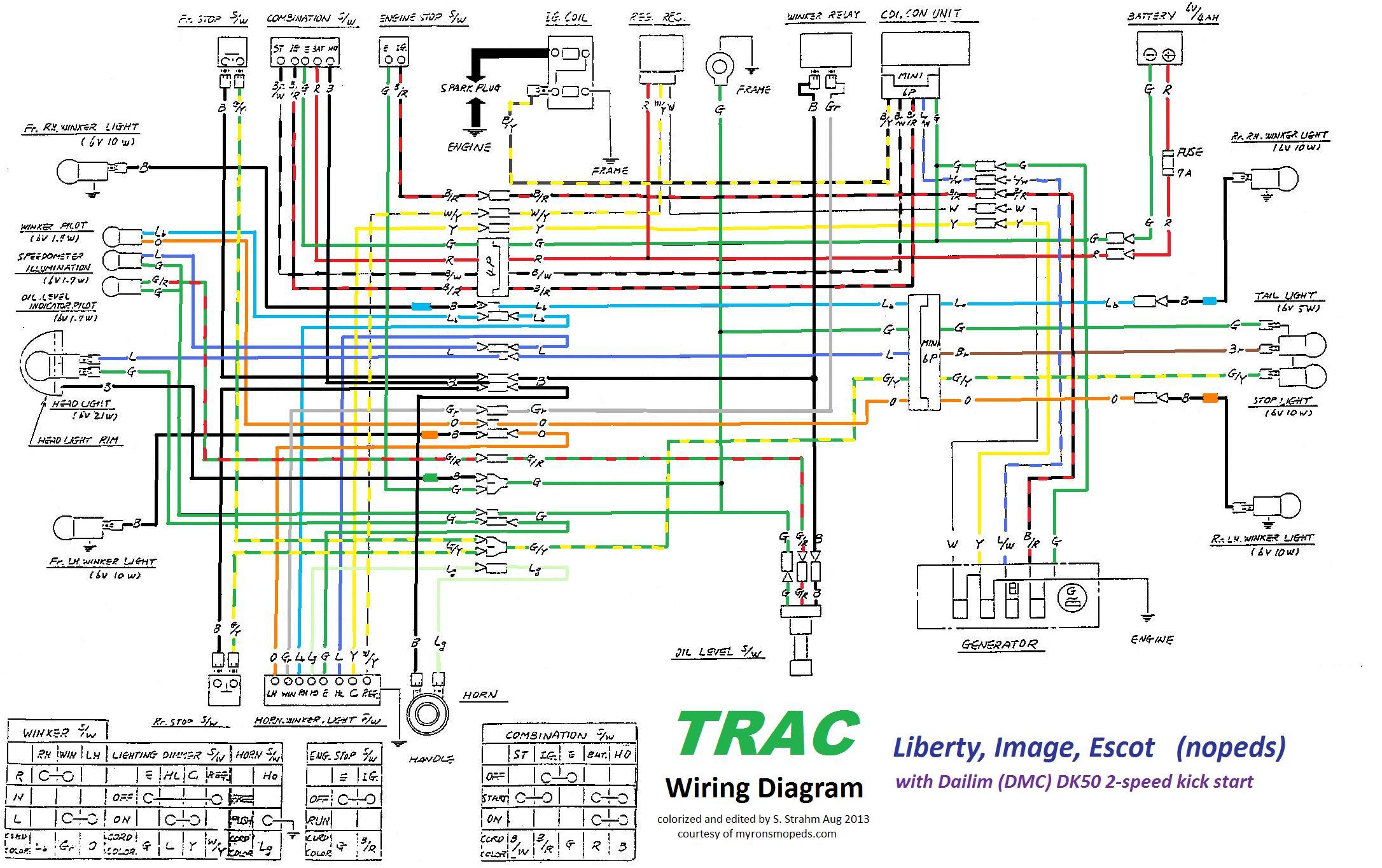
Trac Wiring: Trac mopeds were made in Korea by Dailim (DMC). Early Tracs were a mix of European and Asian components and designs.

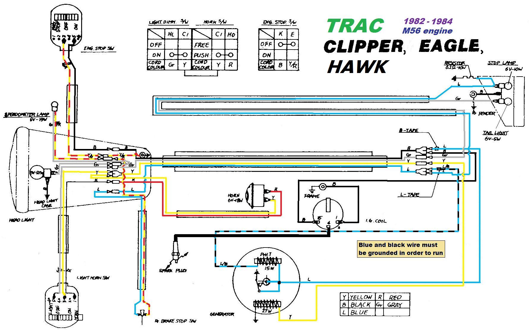
Trac 1982-84 Clipper,Eagle,Hawk
Daelim M56 engine
Bosch 3-wire magneto
external ignition ground
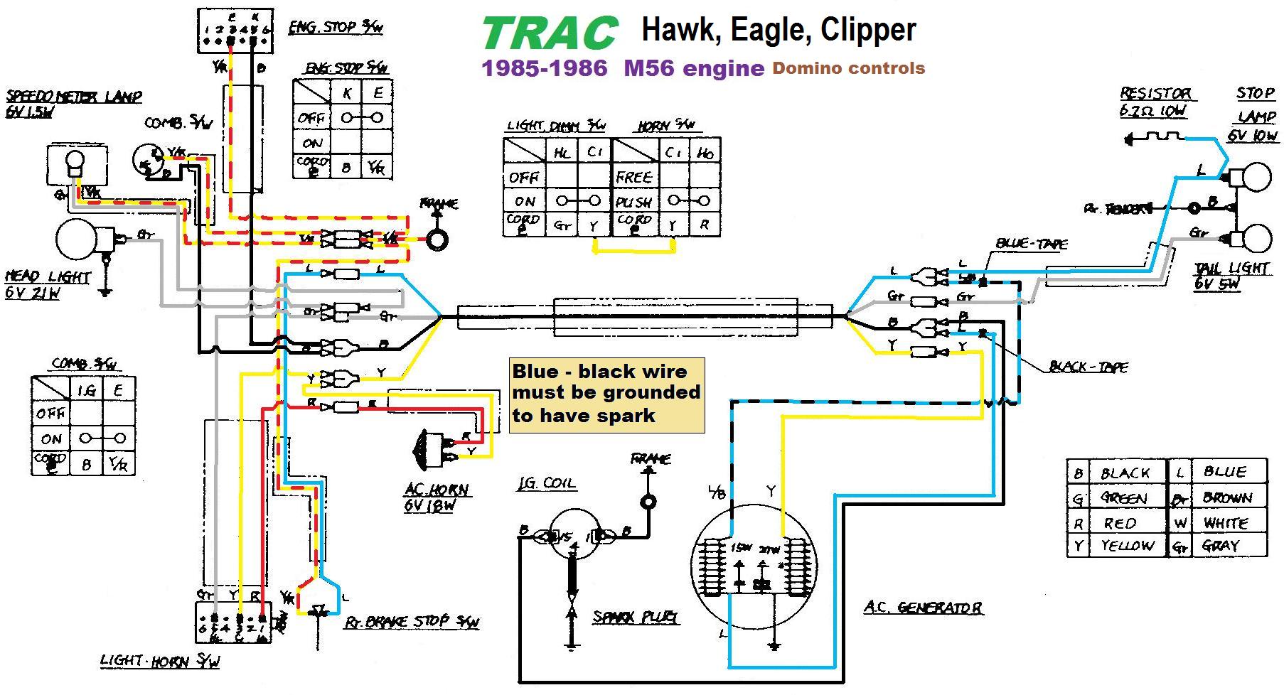
Trac 1985-86 Clipper,Eagle,Hawk
Daelim M56 Engine
Bosch 3-wire magneto
external ignition ground
Later Tracs were all Asian, with wire colors same as Honda.
 The DMC DP50 (one-speed with pedals) used on Olympic, Clipper, Hawk and DM50 (two-speed kickstart) used on Liberty, Image, Escot, engines both had a 5-wire CDI magneto. White = battery charging, yellow = head light, blue/white = ignition pulse, black/red = ignition power, green = ground.
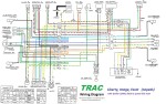
Trac 1986-89 w/signals
Liberty, Image, Escot Daelim DK50 2-speed
CDI 5-wire magneto
internal ignition ground

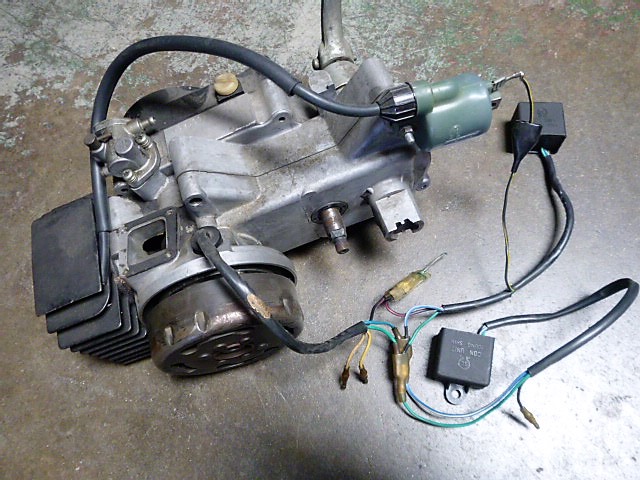
Trac Daelim DK50
wires needed for spark

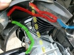
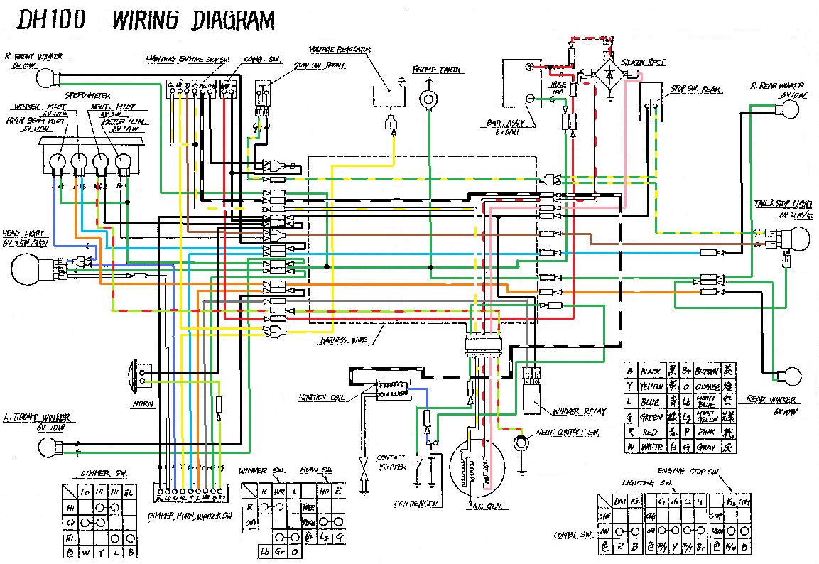
Trac DH100 Super Hawk
3-wire oil bath magneto
points up on the OH cam
6V 6Ah battery, 6V lites
<<There are two CDI units that look the same. Here the key switch is bypassed by joining the two black/red male bullets. The engine stop button (black/white) is also disconnected. This apparatus has good spark, when the wheel is spun counterclockwise by hand. Note that the coil is grounded.
The DMC DH100 (4-speed 97cc 4-stroke overhead cam motorcycle) had a 3-wire magneto/generator down in the oil bath, with external points and condenser up on the overhead cam. Very much the same as a Honda 90, except the Trac had a ignition source coil in the generator, while most versions of Honda 90’s did not . A 1986 Trac DH100 would run with a dead or missing battery, but a 1971 Honda Trail 90 would not. These similar small motorcycles are examples of the difference between a battery ignition and a magneto ignition system.
U=====================
Universal Ign Wiring
Ext or Int Ground
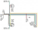
Universal Wiring Harness
brake light wires can be
norm open in parallel or
normally closed in series
Universal Wiring Actual
this is for sale in electrical
also in Morini Wiring
V=====================
Vespa Wiring: There many wiring diagrams with photos and service info. They are located in a separate Service section, under Vespa Electrical https://www.myronsmopeds.com/category/vespa-electrical/
W=====================
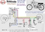
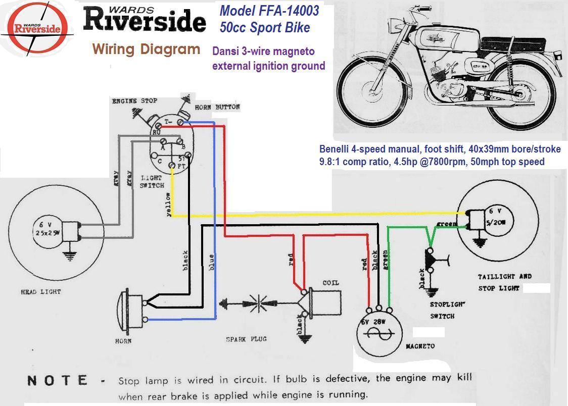
Wards Riverside Wiring
Dansi 3-wire magneto
external ignition ground
Wards Riverside Wiring: Mongomery Wards in the late 1960’s sold a full line of motorcycles and mopeds made in Italy by Benelli (and also early 1960’s mopeds made in France by Motobecane). This is the 50cc sport bike model FFA-14003, a 4-speed foot shift manual clutch motorcycle. Even back then, they used the ignition source coil ground to operate the brake light. Ground the green wire first to get spark.
X=====================
Y=====================
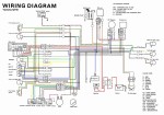
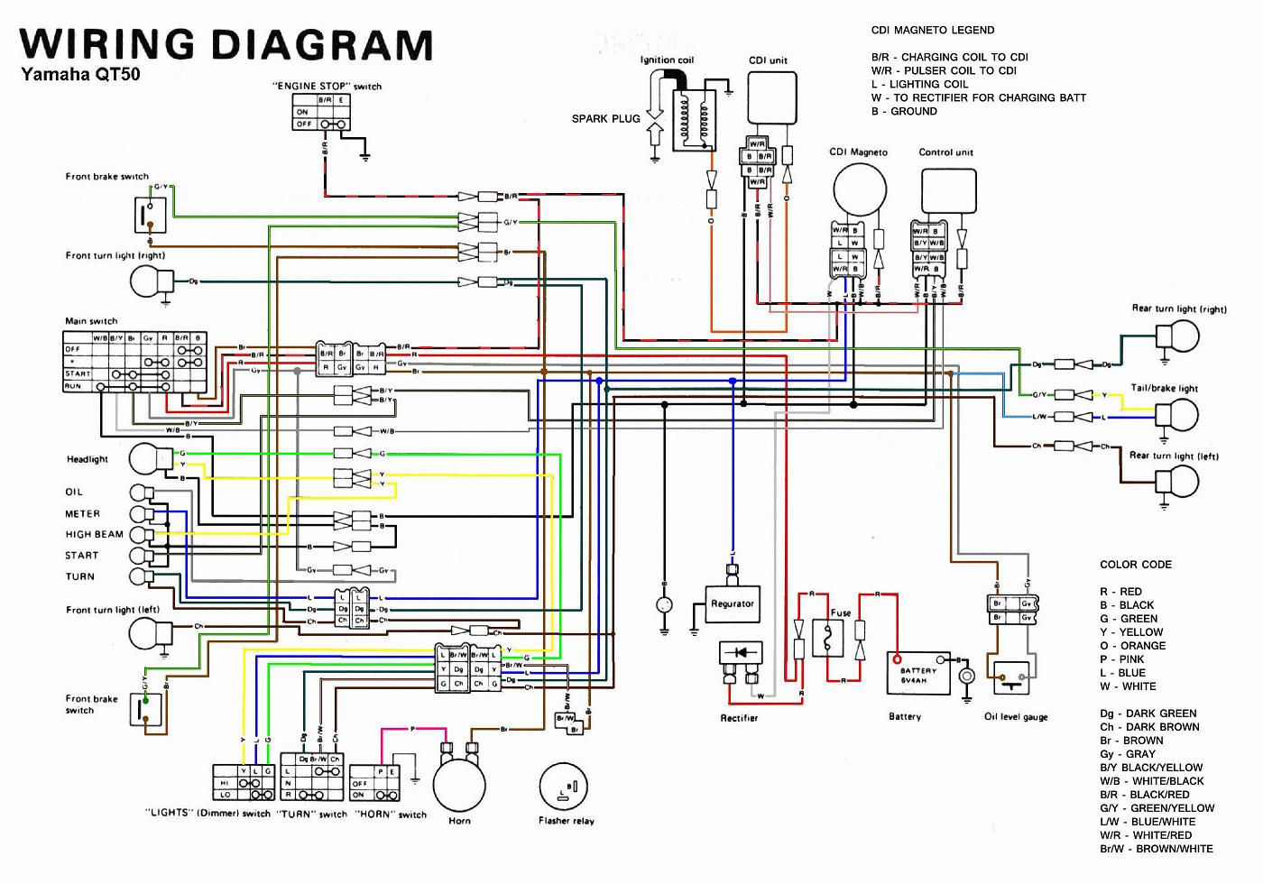
Yamaha QT50 Wiring
Yamaha Wiring: Yamaha made the QT50 Yamahopper moped (actually “no-ped” or “mokick”) from 1979 to about 1983. There are 2 or 3 wiring and electrical equipment versions. more later…
Z=====================
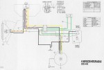
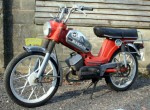
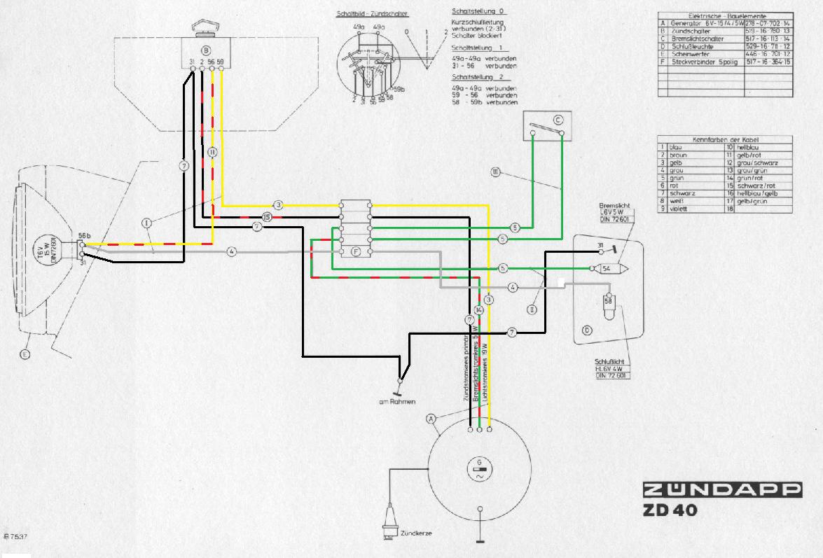
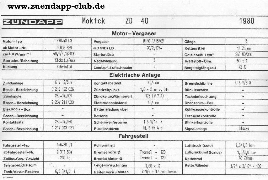
Zundapp ZD40 Wiring
Euro model w/brake light
internal ignition ground
Zundapp ZD40 1980
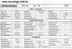
3-speed mokick specs
Bosch 0212 122 026 mag
Zundapp ZD40 1977
pedals,3-spd, alum frame
Zundapp mofas, mopeds, and mokicks were never sold in the US. The “BMW of mopeds” is included in the wiring party because Zundapps are easy to admire! Too bad “ZD40” means 40kph (26mph).
Welcome to Myrons Wiring Diagrams Gallery. Mopeds have strange electrical wiring. Many have “secret” wires that must be grounded to run. Many have switches that normally would turn off something, but instead they turn on something (brake light or horn). Most of the wiring diagrams explain this, when it applies. This “secret wire that must be grounded to run” system is only on most 1970’s and 1980’s US models. The reason for this craziness is that European mopeds do not need brake lights, but US ones do. So many kinds power the brake light from the back side of the ignition source coil. One kind, Puch 77-later, 6-wire, powers the horn from the back side of the ignition source coil. So on a 77-on Puch, if you unplug the horn and push the horn button, the engine dies. Besides loosing spark, older mopeds also often burn out light bulbs. That is because a magneto generator alone, without a battery or regulator, ranges from dim lights at idle, to bright at full speed. So your bulbs are either too dim, or else they burn out a lot. Modern (1990-later) mopeds don’t have the old moped wiring problems. They run a more powerful magneto, 70-80 watts instead of 30-40. All the lights run off one wire, with a 12VAC voltage regulator. To keep the voltage below about 13V, the regulator passes any excess current into the frame where it’s mounted. So when most of the lights are off, the frame is being warmed a lttle. This “regulation by wasting” system is common on motorcycles but not automobiles. Also nothing that the lights do ever matters to the ignition. Magneto ignitions after about 1993 are CDI (Capacitor Discharge Ignition) instead of points. They’re also maintainence free and have easier starting.
 Welcome to Myrons Carb Service and Jetting tutorial. As most of you know, the main function of a carburetor is to blend the gasoline with air to make an explosive mist of super fine droplets. In order to burn all of the oxygen and all of the gasoline, they must be in the right ratio, or else oxygen or gas will be left over, and wasted out the exhaust pipe. The carburetor also has a control valve, in most moped carburetors it is a slide type, that controls the power of the engine. When you want to accelerate, twisting the right handlebar grip towards you pulls a cable that pulls the throttle slide up. This “opens the throttle”, and lets the maximum amount of air get through. Moped and motorcycle carburetors also have a small reservoir of gasoline, called the float chamber or float bowl. An automatic valve attached to a float lets gasoline into the reservoir when the level gets too low, and shuts off the supply of gasoline when the level gets too high. The reservoir insures a fairly constant supply of gasoline, even when the demand changes as when the rider opens and closes the throttle. The float is operated by gravity, so when the bike is laid over on it’s side, and the fuel petcock is on, gas will leak out, either onto the ground, or into the air box and engine, or both. Always turn off the gas (fuel petcock at bottom of gas tank) before transporting the moped.
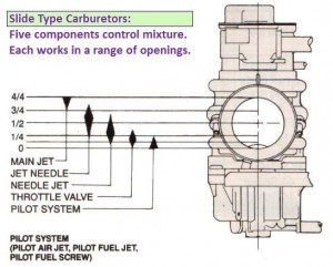


 Welcome


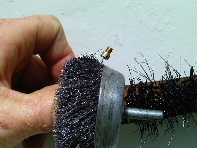
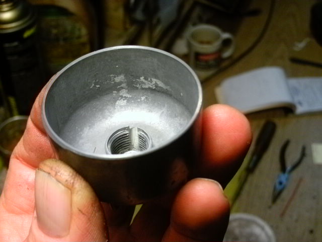
 A better way is with a special sprocket nut, custom made. MM made and sold these from 2003 to 2010, but no more.


