Tomos Throttle Upgrade

August 13, 2008

Tomos 1991-2007 Throttle Upgrade

This is about how to repair an A35 throttle that has a bad “throttle valve”, in case the original part is not available.

Above, the bottom view of the throttle used on all A35 (except A35 Revival) and A55 models from 1992 to early 2008. Everything is black except the light grey “throttle valve”, also known as “sliding block”. It is Tomos part number 223707. Since mid 2008 the controls are different. They say TBS, and the throttle is a wrap-around type, so it has no sliding block.

Above, the same throttle with a pinch bolt upgrade. When the sliding block breaks or strips and cannot hold onto the cable wire, a throttle pinch bolt, 5mm diameter by 7mm long is installed on a new throttle wire just behind the broken sliding block. First a new throttle wire is installed and lubed. The old sliding block must be in otherwise good condition, other than it cannot hold onto the wire. A 5mm diameter by 7mm long throttle pinch bolt is slid over the end of the new throttle wire, and positioned against the sliding block. The wire is pulled taut. The screw is tightened with a small sharp proper fitting screwdriver, very tight. With the engine not running, the throttle is operated to see if it works and feels right. Then the excess wire is cut off, with a sharp wire cutters (diagonals), when the throttle is held at max, engine off. The short tail should be about 1/4″, like shown above. Bend the tail if it hits the grip at max position.

Above left, exploded view. Middle, broken 223707 with pinch bolt back up. Right, pinch bolt 5mm diameter x 7mm.

Warning. Improper installation or using a bigger or different pinch bolt might make the throttle stick or stay on. Many other things can also make the throttle stick, such as lack of lubrication, or a kinked or frayed cable. See Service/Carburetor for info about sticking throttles. Do not let anyone operate the moped if the throttle is sticking. It should always snap back to idle when you let go. This information is for service personnel and competent home mechanics, not just anyone. Please get help if you need it. Use discretion, and use this info at your own risk. The author assumes no responsibility for the use of this information.


Tomos Balanced Clutch Drum

August 12, 2008

The Tomos two-speed automatic dual clutch drum, located behind the bulge in the right side of the transmission cover, is about 4 inches in diameter and made of two stamped sheet steel drums crimped onto a center tool steel precision shaft with gear. In the picture below, the view is of the outboard side, which is the first speed centrifugal clutch side. Flip it over and you would see an identical drum, facing opposite, with a small 1 inch straight-cut gear, the “first speed driving gear”, attached to the inboard side of the dual clutch drum, which is the second speed centrifugal clutch drum.

These drums can be made slightly out of round. They are machined on the inner surface only, where the clutch shoes slip and grab, according to speed. That machining is always perfect, as the inside surface is perfectly concentric with the one-way needle bearing. The proof is there is never any rapid pulsation during clutch slip. So the drum and clutches function perfectly. When the outer surfaces are out of round, the whole bike vibrates or buzzes, and gets worse when the engine is revved up going fast. That buzzing can be felt most in the hands and feet. It can make the mirrors blurry. It can make the speedometer go wild. It can make things on the bike crack, break off, or come loose.

When the drum is a little off balance, and the set of three clutch shoes is also a little off balance, then the vibration felt in the bike can become worse at times, more or less at random. This is because every time the bike slows down, the centrifugal clutches let go of the drum as the spring pulls them inward, and they begin to rotate inside the drum. Then when the bike speeds back up the clutches fly out and grab the drum, because of centrifugal force. But they end up in a new random location in the drum. If the heavy side of the clutch is opposite the heavy side of the drum, then there will be minimum vibration. If both heavy sides are together, there will be the most imbalance and the maximum vibration felt.

Other things can cause excessive engine vibration. Installing a heavier or bigger piston, like a 65cc, is the most common. Running with a loose flywheel or clutch nut is one. The magneto flywheels all seem to be balanced good, although they have not been tested. Using mis-matched clutch shoes is another. Not only should they all weigh the same, but they should all be equal in wear, not one new and two worn out, for example.

Above, the Tomos clutch drum. This one is extremely out of round, so bad you can see it with your eyes. Look at the thick wall on the left. Now compare that with the thin wall on the right side. Clearly the left side is heavier! When they’re bad they’re usually less than half this much. The out of balance clutches began around 2008. Before that, from 1976 to 2007 there was never any noticeable balancing or vibration problem. The A35 (1991-2006) and A55 (2002-later) have the same clutch drum. The A3 (1976-1990) one looks the same but parts of it are smaller or thinner.

Pressed into the center of the clutch drum is a precision roller clutch, a needle bearing that only turns one way. In the picture below, the roller clutch is installed correctly, with the plain side facing out, and the writing side facing inward. When you rotate an installed Tomos clutch drum clockwise, it engages the crankshaft. When you rotate it counter-clockwise, it spins free. When a Tomos engine seizes or hydraulics (that’s when the piston slams into incompressible liquid – gas or oil), the roller clutch can become damaged. It usually becomes tight or frozen. When a Tomos roller clutch is frozen, the bike will run fine but won’t go into neutral when you slow down to stop.

How to “balance” the drum:

A machine shop or a home machinist with a lathe, can perform a precision cutting operation. The drum is held by it’s inner surface, and turned in a lathe. The high parts of the outer surface are “skimmed off”. Try to leave the lowest part uncut, to give it the most strength.


Tomos Stripped Driveshaft

August 12, 2008

On pedal models only, not kick models, during the years 2008-2009, occasionally a driveshaft 223453 would become stripped at the ring of ramps needed for forward pedalling. This can never happen on kick models, because they do not have a ring of ramps. When the ring of ramps becomes stripped, the bike runs fine and kick starts backward fine, but the pedals just spin free going forward and do not propel the bike forward at all.

Left is a 223453 driveshaft brand new. Right is a 223453 stripped at the ring of ramps. No ped, only mo!

Some people live with it like that because it’s expensive to repair. The cast iron chips need to be flushed out, or else one chip can damage any one or even all of the gears. It’s too big a gamble to leave them laying in the bottom back corners of the transmission compartment. If the bike is ever leaned way over, the little iron chunks and bottom oil sludge will be poured over the gears.

More to follow…


Tomos A55 Derestriction

August 11, 2008

1. Removing intake air flow restrictor

This is the 2010-later carb, with red silicone over idle mixture screw. The PHVA14 has an idle speed screw, with a big knob sticking out for the rider to use occasionally, and a idle mixture screw, recessed with a slot head, for the service technician to use.

The “elephant trunk” restrictor is exposed, a hidden part of the junction sleeve 233748 that joins the air filter/silencer to the carburetor.


This is after the rough cut.

This is after smoothing and rounding with a rotary file.


2. Replacing the rear sprocket

Sprint, ST and LX models come with 28 tooth. Replace that with 22 tooth and subtract 3 chain links.

Revival and Streetmate models come with 31 tooth. Replace that with 24 tooth and subtract 4 links.


3. Shortening the stock exhaust

Only welders and metal workers can do this. But the benefits are huge. Speed increase from 37 to 43 mph.


Tomos Wiring Diagrams

April 13, 2008

Welcome to New Tomos Wiring Diagrams, 1992 and later, A35 and A55 engines (not A3 1976-91). 

Tomos 1992-93

Tomos Bullet A35
Bullet TT, 1992-93

Tomos Colibri 1992-96

Tomos Colibri
1992-96

Tomos Sprint 1993-97

Tomos Sprint 1993-97

Tomos Targa 1994-95 Tomos Targa LX 94-95

Tomos Targa 1994-95
Tomos Targa LX 94-95


Tomos Targa 1996-97 Tomos Targa LX 96-97

Tomos Targa 1996-97
Tomos Targa LX 96-97

Tomos Sprint 1998-01

Tomos Sprint 1998-01

Tomos Targa 1998-01 Tomos Targa LX 98-01

Tomos Targa 1998-01
Tomos Targa LX 98-01

Tomos Revival 2001-02

Tomos Revival 2001-02


Tomos Revival 2002-07

Tomos Revival 2002-07

Tomos Sprint 2002-07

Tomos Sprint 2002-07

Tomos Arrow 2005

Tomos Arrow 2005

Tomos Arrow-R 2006-08

Tomos Arrow-R 2006-08


Tomos Streetmate 05-07

Tomos Streetmate 05-07

Tomos Streetmate 08-12 Tomos Str.mate-R 08-13

Tomos Streetmate 08-12
Tomos Str.mate-R 08-13

Tomos Revival 2008-12+

Tomos Revival 2008-12+

Tomos Sprint 2008-13 Tomos ST  2008-2013 Tomos LX  2008-2012

Tomos Sprint 2008-13
Tomos ST 2008-2013
Tomos LX 2008-2012


Peugeot Ignition Upgrade to External Transformer

July 22, 2007

Please, beware. Before you blame the magneto or the coil, always first connect the black engine wire to ground, with an clip lead or something equivalent, and disconnect the brown engine wire. This isolates the engine from the rest of the bikes wiring. Usually this will fix the problem of no spark. Usually it’s just a loose brake light/ignition ground wire, often inside the headlight, or unplugged at the brake light switch and unplugged at the brake light (or the brake light filament burned out). Read more in the ignition sections.

Welcome to Myrons Mopeds Peugeot Ignition Upgrade tutorial.  This is an explanation of how to repair 1976 to 1979 Peugeot two-coil ignitions, with a clear-coated-copper colored lighting coil on the bottom and light golden colored ignition coil on the top. After 1979, Peugeot 103 & 102 mopeds came with a “star” magneto, where several coils are arranged radially like the rays of a star. Those 1980 and later “star” magnetos already have this external transformer upgrade.

Above is the parts book exploded view of the 1976-79 Peugeot 103 magneto, with external ground (the black wire on top). On the bike, this whole assembly is rotated 80 degrees clockwise. The fingernail-sized notch in #2 stator plate, for the spark plug wire and grommet, should be in the 12 o’clock position, straight up, not in the 9:30 position shown here.

Below is the 1980 Peugeot 102/103 magneto, with internal ignition ground, that always has spark no matter what the lights are doing. At bottom is #32, the external transformer, aka “the coil”, that’s bigger and isolated from the engine heat. Both of these Peugeot factory upgrades, internal ignition ground and external transformer coil, made the 1980’s bikes more reliable than the 1970’s models. Most Peugeot 103 mopeds in the USA were the early years 1976 to 1979. In 1981 Cycles Peugeot USA stopped selling motorized bicycles, but continued their main product, bicycles. So the newer magneto/ignitions were in the US for only one year, while the early magneto/ignitions were in the “boom” years.      

What is a “Upgrade to External Transformer”?  All ignitions have a transformer, commonly called “the coil”. The transformer changes the pulses of electricity from low voltage to high voltage. On most mopeds and larger engines, the transformer coil is located outside the engine. On Peugeot, some older mopeds, and most hand-held gardening equipment engines, the transformer is located inside the engine, to save space, weight, and cost. If the high voltage spark plug wire comes from inside the engine, like on a chain saw, then it has an internal transformer. If the spark plug wire comes from outside the engine, then it has an external transformer. The Peugeot Ignition Upgrade is modifying the internal transformer to work with an external one, and then adding an external transformer (ignition coil), mounted on the frame, just right of the carburetor.

Why does it need an upgrade?  The original coils go bad, sending sparks that damage the points and condenser, or sparks that jump (arc) through the coil and into the aluminum wall of the stator plate. The result is the engine misfires (hiccups), or worse, spits and sputters chaotically, unpredictably, especially when hot. The cause is tiny cracks in the insulation that let sparks escape. Some old coils go bad this way, by deterioration from old age. Peugeot and certain other “new old stock” coils are no good, because of their age, 35 years old (1977 to 2012).

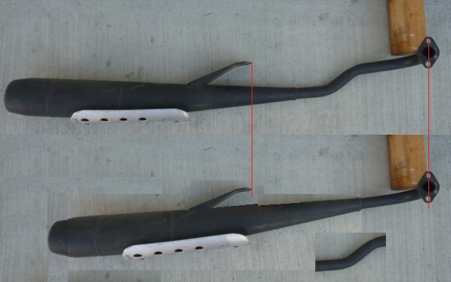
Below is Myrons Mopeds display board, normally hanging above and near the cash register at the shop. It shows the original Peugeot ignition on the left, and the upgraded Peugeot ignition on the right, before and after. 

Notice that everything is the same, except on the upgrade ignition, (1) the coil has a horizontal cut through it, and (2) the brown (maroon) ignition wire has a “T” with a branch going to the new external ignition coil (red). Those two things are all that’s different. They are easy to say, but not easy to do.

At the bottom of the display board is a Peugeot ignition coil (internal transformer) with it’s outer (secondary) windings completely removed, exposing the few hundred inner (primary) windings. The outer windings do not need to be removed completely. Each of the thousands of hair-thin outer (secondary) windings needs to be cut. If too many are left uncut they can still cause some residual misfiring. Below is a close up of the Peugeot ignition coil with it’s outer (secondary) windings removed. Some of them are shown at left, and below embedded in the outer insulation shell. They are hair thin, and clear coated with varnish. Some of the individual hairs are barely visible.

Below is that same coil, showing inner windings even with, or a hair below the first steel plate.

What are the symptoms?  Very often the points will have a white crust from sparks arcing across. Below left is an example of the white frosting around the outer edge of the round contacts. When the engine is running, the whole magneto might be lit up in blue flickering light from the strong sparks jumping, brighter than the spark plug spark. Normally the points spark a little, but not steady and bright. The sparks that jump the points also damage the condenser. You can’t see the little burnt spots inside the condenser, but they’re there. Another symptom of a bad Peugeot ignition coil is black dots or lines near the high voltage output wire. Below middle and right, are two bad coils with burnt spots on the back side where sparks were escaping. It’s only about 1/2 inch away from the stator plate aluminum wall. When a spark jumps there, it makes the spark plug not fire.

Why does it often happen only when fully hot?  When solid things get hot they expand slightly. Any microscopic cracks that are closed tight when the engine is cold, will be opened up wide when the engine is fully hot. Open cracks in the insulation are shortcuts for sparks to jump through, or leak out of, instead of going to the spark plug and jumping the gap there. Usually it takes 10 to 20 minutes before a misbehaving Peugeot cuts out and leaves the rider to pedal back home. Once back home and cooled down it might re-start and run fine.

How it’s done:


1. Remove the flywheel nut. An impact wrench, air or electric is needed, because the flywheel turns with the nut. Or else a piston stop is used in the spark plug hole to stop the piston from rising, and the flywheel from turning. Put oil on the threads before and after removal.

2. Remove the flywheel. There’s no key to locate where it goes (what timing angle) on the crankshaft. A flywheel puller tool pulls on the center threaded hole in the flywheel while a bolt pushes on the crankshaft.

3. Remove the stator assembly. Two slot head screws secure the stationary part of the magneto to the engine case. Check if the threads on the crankshaft got damaged during the flywheel removal, by screwing the M10 x 1.00 flywheel nut on with your fingers. Often the threads are damaged (flared) from the removal and a M10 x 1.00 die is needed to repair the threads. In severe cases, careful grinding and rethreading are needed. That is very difficult/expensive but so is a new crankshaft.

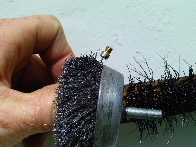
4. Cut through the outer windings. A hand-held disk grinder is what Myrons uses. The cut can and should be wide, so you can see what’s at the bottom. Below left is a coil that is cut to a perfect depth on the sides, but needs more depth in the middle. The perfect depth is the gold colored insulation layer that lies above the inner (thick) windings, and below the outer (thin) windings. Below right is a coil that is cut too deep. It’s only perfect below the P in the word “deep”. The individual thick windings are visible. Some of the first layer of inner windings is cut through. Also there are cut marks in the steel plate, near the bolt holes. If the cut was made farther away from the bolt holes, either way, then cutting to the depth of the steel plate would not be too deep (because the windings are rounded).


Below is a Peugeot coil cut just almost perfect, with only a few outer windings still showing. Some lines of gold plastic are visible at the very bottom of the trench, surrounded by the copper of the outer super fine hair thin (invisible) windings.

The above example also shows Myrons technique of cutting the coil in place, without removing it. When the cut is just above the 7mm hex M4 nuts, the proper depth is near the level of the steel plate.

5. Replace the condenser.   Since the display board was made, Peugeot 20mm condensers have become not available. So the board does not show how an external automotive condenser can replace the original burned out internal one. Any automobile from the 1950’s and 60’s has a suitable condenser. There are different mounts. You must mount it, somehow, onto or near the external ignition coil, which is grounded to the frame. The condenser shell must be grounded solid to the frame. Another “T” can be made from the brown wire, for the external condenser. The original condenser should be removed, and the three wires that went to it all soldered to each other and covered with shrink wrap and positioned so that they never touch or rub against anything, especially the flywheel, and stay there forever.

6. Put the flywheel back on.  Clean the crankshaft taper and the flywheel center tapered hole. Clean the points and check them with an ohmeter for continuity, both open and closed. Clean and grease the points cam with high melting point silicone grease, for points. With the spark plug removed, locate top dead center, by feeling the top of the piston with a pen or pencil. While holding the crankshaft at the exact TDC position, place the flywheel on the shaft with the fire mark (line) on the flywheel 7/8 to 1 inch away (toward the front of the bike) from the rubber grommet where the original spark plug wire came out of. While holding both the crankshaft and the flywheel in that position, strike the center rivets of the flywheel with a steel hammer. This will make it “stick” to the tapered crankshaft.

7. Put the flywheel nut back on.  In the same way it was removed, either with a piston stop or with an impact wrench, tighten the M10 x 1.00 flywheel nut. Do not hold onto the flywheel, or it might slip and change the timing setting. Once tight, check if the mark on the flywheel is still 7/8 to 1 inch in front of (toward the front wheel) of the mark on the engine (which is the pointer on the black rubber grommet for the original spark plug wire). Once the nut is fully tight (25 ft lbs) the flywheel never slips.

8. Adjust the points. Adjust the points gap until they open on the mark. An ohmeter across brown wire and ground, with the black (ignition ground) wire unplugged, will read near zero when the points are closed and near infinity when they’re open. There are some triangular notches for prying the points by twisting a small flat head screwdriver. The more wider the points gap is, the earlier they open. Too wide a gap means they’ll open before the mark. Too small a gap means they’ll open after the mark. The flywheel rotates clockwise, when viewed from the right side of the bike. As the piston rises, the points are closed. When the piston gets almost at the top, at 1.5mm BTDC, which is about 1 inch along the edge of the 5 inch flywheel, the points open, and the marks line up. Set the points to make that happen and tighten the screw.

9. Install the external coil (and condenser). Many (1978-79) Peugeots already have a mounting bracket for the external coil. Some (1976-78) Peugeots do not have any coil mounting bracket. Then one from a Puch, or a custom made bracket, must be welded on exactly right, to barely fit under the right side engine cover.

10. Reconnect the wires and put the spark plug back in. Always ground the black wire if there is no spark. It gets a ground in the left headlight bolt. The ignition ground black wire is often loose there, because tightening the headlight bolt makes the inside locknut looser. Always do this first, way before suspecting somethings wrong in the magneto. If the engine looses spark when idling slow, at the instant the brake is applied, then put in a new NGK B6HS spark plug. If it still does it, reduce the spark plug gap a little.

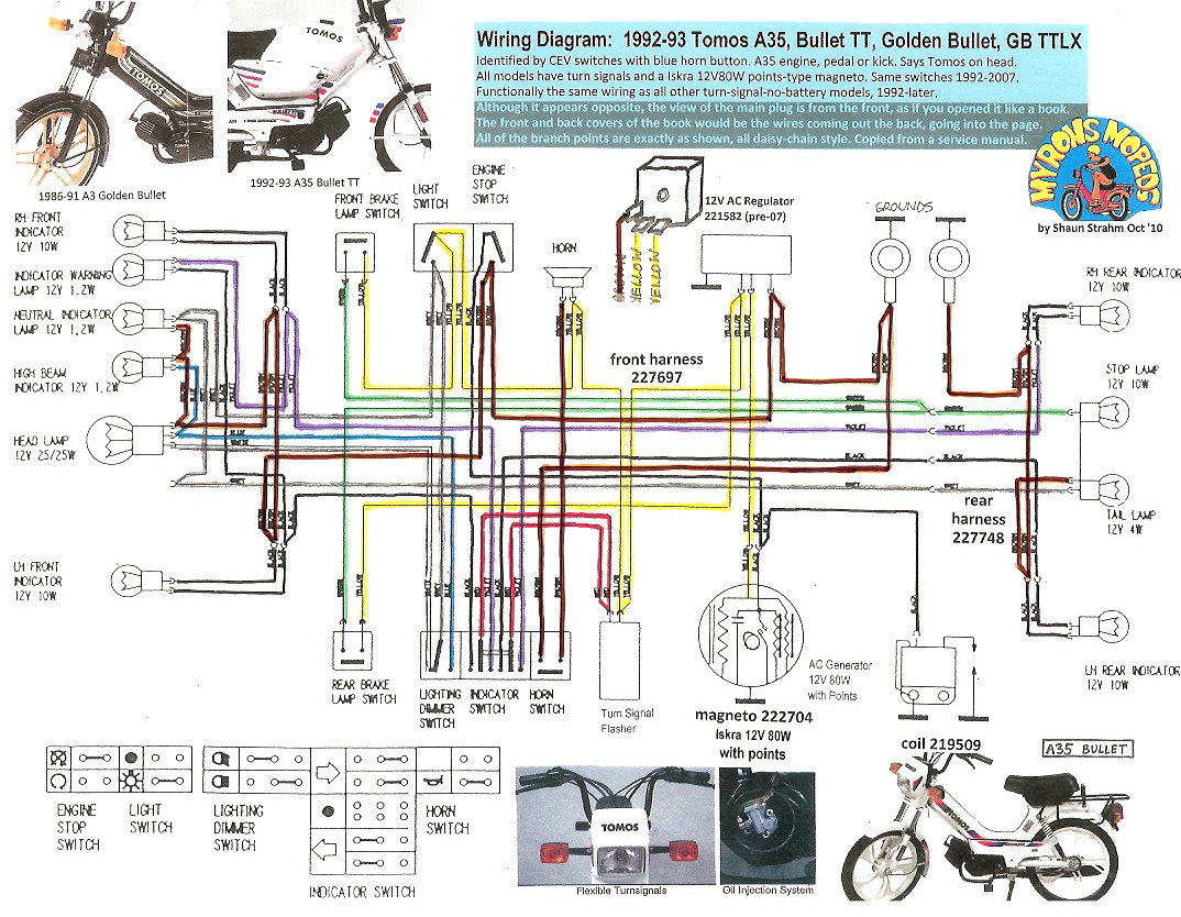
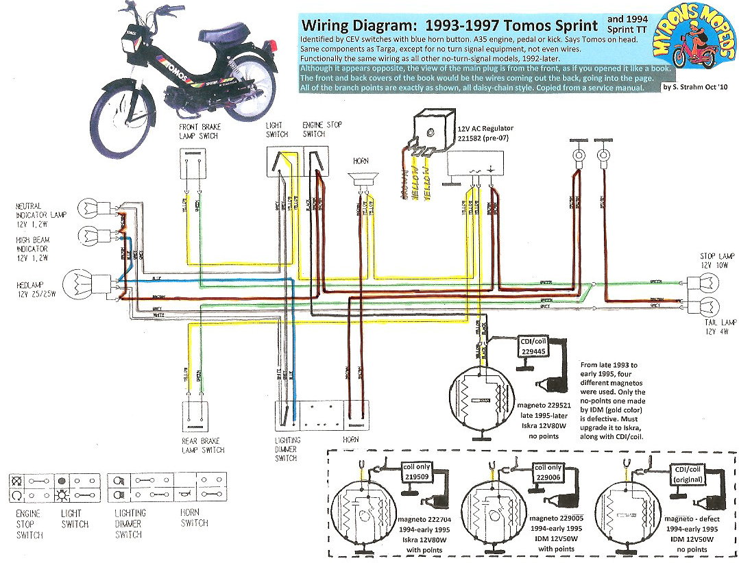
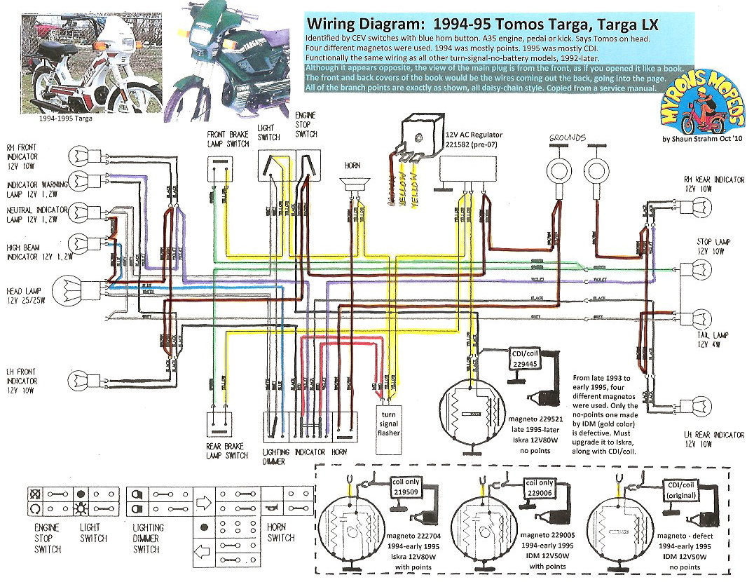
 Are there other ways to do it?  Yes. Instead of slicing the original coil, a Puch ignition source coil can be used. It must be from a 6-wire 1977-later, with a blue and a blue/black wire, not a 4 or 5-wire 1977-earlier, with only a blue wire. The bolt holes are closer together on Puch, about 52mm instead of Peugeot’s 55mm, but the bolts bend in and still work. The clearance between the stack of steel plates and the flywheel is much more, with the Puch coil, but it still gives a good strong spark. Another way to do it is to swap out the entire magneto for a 1980 “star” magneto, if you can get one, then rewire the brake light the “1980 way”, which is right and left momentary closed switches in parallel, and brake light in series with that, rather than the “1976-79 way”, which is right and left momentary open switches in series, and the brake light in parallel with that. See more in wiring diagrams.

What external coils will work?  Any 1970’s or older moped or small motorcycle, with magneto and points ignition, external coil will work. More modern 1980’s and later CDI (capacitor discharge ignition) coils are too small. Car coils are too big. The best kind is the Bosch coil (transformer) used on Puch mopeds. The worst are certain generic India or China made ones, with a weaker spark.

Where did this idea come from?  Starting around 1980, Shaun used to replace a lot of Peugeot condensers, like over 100. Sometimes the points would still have arcing, even with a new condenser. When that happened, 2 or 3 condensers, connected in parallel and externally mounted, were needed to stop the misfiring. Trouble was, the new condenser(s) would not last long. Soon Shaun realized that the Peugeot coils were sending sparks to the new condensers and causing them to “burn out”. When Cycles Peugeot, western USA, moved out of Compton CA, Royal Cyclery bought plenty of new Peugeot coils, like 100, and lots of new complete stator assemblies, like 50. These new original parts lasted into the late 1980’s. By then some of the new coils were bad almost right out of the box. Out of desparation, in about 1988, Shaun got the idea of changing to a different source coil, since all of the Peugeot ones were turning out to be bad. He found that of all the different moped source coils at Royal Cyclery, only the Puch 6-wire one was suitable. All others were either too small, too scarce, or did not have the external ground blue/black wire needed to operate the Peugeot brake light and be compatible with the Peugeot wiring. Gradually through the 1990’s all the Puch source coils got converted to Peugeot upgrade ones. By the late 1990’s there were almost none available. Shaun did about 50 Peugeot Ignition Upgrades from 1988 to 2000 using Puch source coils. Again out of desparation, in the year 2000, he got the idea to use the core of the Peugeot one. He found by trial and error how to cut away the outer windings and re-use the core as a source coil. From 2000 to 2010 Myrons Mopeds has done about 80 Peugeot Ignition Upgrades, recycling the Peugeot coil by cutting it, in place. Now this highly valuable information is free to the public, courtesy of Myrons Mopeds. May your Peugeot 103 never spit, sputter, or say bad things again!


Jet Drills

January 27, 2007


Above, a Tomos A55 idle jet (M4 thread) is physically bigger than a Puch Maxi main jet (M3.5 thread), but the hole size is much smaller. The photo shows how the #25 jet, 0.010" (ten thousandths of an inch), will allow the thinner wire of the wire wheel to pass through the hole, but not the thicker wire of the wire brush. This is a useful cleaning technique.

Above, a Tomos A55 idle jet (M4 thread) is physically bigger than a Puch Maxi main jet (M3.5 thread), but the hole size is much smaller. The photo shows how the #25 jet, 0.011″ (eleven thousandths of an inch), will allow the thinner wire of the wire wheel to pass through the hole, but not the thicker wire of the wire brush. This is a useful cleaning technique.

This will help you visualize how small these drills and jets are!

Moped main jets range from 0.018″ (#77 drill) to 0.026″ (#71 drill). 

Moped idle jets, like Tomos A55, are 0.011″ (smaller than #80).

An average human hair is 0.003″ (three thousandths of an inch).

So moped jet holes are 4 to 9 hairs wide!

Shauns well used jet drill container from the 1980's

Shaun’s well used drill container from 1987


Jet Drills: All through the late 1980’s and 1990’s, Shaun (at Royal Cyclery and later at Myrons Mopeds) used the USA-made jet drills to service carburetors. The drill sizes are an American wire gauge. They did not vary in size. Those 20-piece Drill Sets 61 to 80, cost $40 in 2015, $33 in 1998. and $29 in 1987. Some are in clear plastic round dome containers, and some are in conventional metal drill set boxes.


Drill Set 61-80 USA-made

Drill Set USA-made

Jet Drills made in China

Set 1 China-made

China-made Drills: In the 2000’s there were many China made tools sold in “surplus” tool stores. The China made 20-piece Drill Sets 61 to 80, sell for $7 to $10, or one fourth as much. They have an excellent blue plastic container, that only lets out one at a time. But the drill sizes are all wrong. From about 2010 to 2014, Myrons Mopeds sold these inexpensive drill sets, not knowing that the drill sizes were inexact, to say the least.

So although the China sets cost one forth as much, they only have about seven or eight different sizes, and they lack the smaller sizes below 0.4 (or sometimes 0.6) mm. Each set is different.


Jet Drills made in USA

Jet Drills made in USA

Set 2 China-made

Some have poorly made drills, twisted funny, bigger at the cutting end, or lumpy, varying in thickness. Some have poorly made cutting tips, so they might wander, grab and break, or not cut well.

Despite the poor quality and inexactness, the inexpensive drills are still useful for cleaning purposes, but not for measuring and maybe not for drilling. Fortunately, brass carburetor jets are the easiest thing to drill, with a drop of oil and a pilot hole already there.


Micro Drills and Wires for Sale Individually

These drills are measured at the shank (the smooth part). At the cutting edge they are 1 or 2% bigger.

These wires are steel guitar strings, cut into 5 inch lengths. 

“Metric” jets have a number that literally means hundredths of a millimeter, so a 64 jet is 0.64 mm.

Micro Drills for sale

inch   mm/#  price     moped jets that it cleans
0.011   wire     N/A Gurtner Motobecane diffuser – two idle holes (.013)
0.0135 #80  $6.00
0.0145 #79  $5.00
0.0157 0.40  $3.00 Dellorto 38 (.0162), Bing 42 (.0162)
0.016   #78  $4.00 Dellorto 40 (.0168), Bing 44 (.0167)
0.017   wire  $0.50 Dellorto 42 (.0177), Bing 46 (.0175)
0.018   #77  $3.50 Dellorto 44 (.0186), Bing 50 (.0188)
0.019   ——  $2.00 Dellorto 46 (.0194), Bing 52 (.0194)
0.0197 0.50  $2.00 Dellorto 48 (.0202), Bing 54 (.0200), “Metric” 51 (.0201)
0.0200 #76  $3.50 Dellorto 49 (.0207), Bing 56 (.0206), Gurtner 210=52 (.0210)
0.021   #75  $4.00 Dellorto 51 (.0215), Bing 58 (.0213), Gurtner 220=54 (.0220)
0.0225 #74  $5.00 Dellorto 55 (.0231), Bing 62 (.0229), Gurtner 230=56 (.0230)
0.023   ——  $2.00 Dellorto 56 (.0235), Bing 64 (.0234), Gurtner 240=58 (.0236)
0.0235 0.60  $2.00 Dellorto 58 (.0242), Bing 66 (.0239), Gurtner 245=59 (.0239)
0.0235 0.60  $1.50 Dellorto 58 (.0242), Bing 66 (.0239), Gurtner 250=60 (.0242)
0.024   #73  $3.00 Dellorto 60 (.0247), Bing 68 (.0248), “Metric” 63 (.0248)
0.025   #72  $3.50 Dellorto 62 (.0255), Bing 70 (.0254), “Metric” 65 (.0256)
0.026   #71  $4.50 Dellorto 66 (.0268), Bing 74 (.0267), “Metric” 68 (.0268)
0.0275 0.70 x N/A  Dellorto 70 (.0280), Bing 78 (.0280), “Metric” 71 (.0280)
0.028   #70  $4.00 Dellorto 72 (.0287), Bing 80 (.0287), “Metric” 73 (.0287)
0.0292 #69  $4.50 Dellorto 78 (.0306), Bing 84 (.0301), “Metric” 77 (.0303)
0.030   wire     N/A Dellorto 80 (.0312), “Metric” 79 (.0311), Gurtner K80 (.0311)
0.031   #68  $4.50 Dellorto 82 (.0318), “Metric” 81 (.0319)
0.0315 0.80  $2.00 Dellorto 84 (.0324), “Metric” 82 (.0323)
0.032   #67  $3.00 Dellorto 86 (.0331), “Metric” 84 (.0331)
0.0325  —— $2.00 Dellorto 88 (.0337), “Metric” 86 (.0339)
0.033   #66  $4.50 Dellorto 90 (.0343), “Metric” 88 (.0346)
0.034   wire     N/A “Metric” 90 (.0354)
0.035   #65  $3.00 “Metric” 92 (.0362), Gurtner MB (side mount) diffuser (.0358)
0.0354 0.90  $2.00 “Metric” 94 (.0370)
0.036   #64  $3.00
0.037   #63  $2.50
0.038   #62  $1.50
0.039   #61  $1.50
0.0394 1.00  $1.00


Deluxe 40-piece Micro Drill Set

Jet Drills 80-72 and 71-60

Myron’s Mopeds two case deluxe micro drill set, 80 to 72 (small) and 71 to 60 (large) plus many in-between sizes.
Price none, sorry no more.

Slide clear top plastic until hole is over drill (and pointer is on desired drill number). Only lets one drill out at a time. Never take out more than one at a time, or they can get mixed. The case keeps them organized. If any get lost, dull, or broken, individual drills can be bought at some hardware stores for $3-$4 each.

Useful for sizing to tell how big a jet really is (sometimes they’re drilled out or labeled wrong).

Useful for cleaning varnish or corrosion coating the inside of an old jet. It doesn’t really clean out any other way. The drill is used as a file, held with a needlenose pliers.

Useful for drilling jets to make a new size, as an alternative to buying ones. The drill is held with a needlenose pliers, and the jet is rotated with your fingers, with a drop of oil. To go down in size, fill the hole with solder and re-drill it smaller.


Here is a pin vise, a mini drill chuck, price $8


Other Tools for Cleaning Jets

Using a micrometer to measure a 0.017 wire

Using a micrometer to measure a 0.017″ wire

Guitar steel string 17 thousandths of an inch

Guitar string

Guitar Steel Strings in the smaller sizes are excellent tools for cleaning small holes. Here is a 0.0170 inch steel wire guitar string, perfect for cleaning out a 1974-85 Tomos stock jet size 46 that has a 0.0175 inch hole. A Honda Express NC50 (Keihin) carburetor, has a long brass idle jet tube with a tiny jet hole at the far end, too far for a drill to reach. For that, only a 2 or 3 inch piece of 0.010″ steel guitar string will reach to clean it. Ultrasonic cleaners, carb spray, or soaking are not effective for that. Other examples are a Sachs 52 jet 0.0190 would be cleaned by a 0.018″ wire, or a Motobecane 230 jet 0.023″ would be cleaned by a 0.022″ wire. The wire has to be a little smaller than the hole. Plain steel strings range from 0.008″  to 0.017″ in steps of 0.001″. Wound strings range from 0.017″ to 0.065″. 


Torch Tip Cleaner Set

Torch Tip Cleaner Set

Root Canal Files

Root Canal Files (say ahhh)

Welding Torch Tip Cleaners are another excellent tool for cleaning small holes. The tip has a cutting surface but not the sides. So it is made to clean the hole without widening it.

Wire Feeler Gauge Sets: There are also wire gauge measuring sets that look the same as the torch cleaner set shown.

Dentist’s Root Canal Files are also good for cleaning small holes. Color coded files range from 0.06 to 1.10 mm (0.0024 to 0.0433 inch).