Introduction

June 16, 2015

Welcome to Myrons Service Department. Mopeds are easier to work on than cars. You don’t have to lay under them and get dirt in your eyes and oil in your hair.

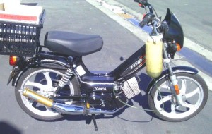
Myrons Mopeds has stopped doing most moped service. That has made things difficult for many people. So here and throughout the website, plenty of useful information is provided, or is being planned, to help people repair mopeds and find parts. Shaun has been making moped lists and organizing information since the 1990’s. To start with, here is the “universal owners manual” he wrote in 1999. Read that and then read the actual owners manual for your model of moped. Some of the original manual info is obsolete, like oil types. Most of the Myrons Mopeds service information is intended to supplement the original service manuals.


Moped Owners Manual and Introduction 

by Shaun Strahm, Myrons Mopeds, 1879 W Commonwealth #L Fullerton CA   714-992-5592   Dec 1999

TWO-STROKE ENGINES:

Mopeds have two-stroke engines. Outboard boats, chain saws, weed wackers, and many small motorcycles also have two-stroke engines. It’s called “two-stroke because the spark plug fires every two strokes of the piston (down & up). Four-stroke engines, like cars & lawnmowers have, fire the spark plug every four strokes of the piston (down, up, down, up). This is why two-stroke engines sound more like buzzing insects, while four-strokes sound more like a drum roll.

Two-stroke engines run on gasoline with two-cycle oil mixed in, or have oil injection. A two-stroke engine does not have motor oil in the crankcase, like a four-stroke does. Instead the crankcase contains the gasoline and air mixture, with a little bit of two-stroke oil added in. After the two-stroke oil coats the crank bearings and piston it is burned along with the gasoline. The burning of oil makes a little bit of smoke in the exhaust, which is normally barely noticeable.

TWO-STROKE OIL:

The most important thing you can do to keep your moped healthy is to use a good quality two-stroke oil and mix it in the correct amount of 50 to 1 (2.5 ounces per gallon). This will make the engine stay strong and last a long time, and help prevent carbon build-up inside the exhaust. The oil we sell and recommend is called Champion 2-Cycle Oil and comes in small 2.5 oz bottles for $2, and large 12.5 oz bottles for $5. Some of the highest mileage mopeds I have seen over the years have used this oil, which is a petroleum based oil with expensive synthetic additives. Pure synthetic oils are also very good. You buy good quality two-cycle oil at motorcycle and lawnmower shops. Auto parts stores usually only carry ordinary less expensive blends. Grocery and drug stores also carry cheap two-cycle oil.

OIL INJECTION:

If your moped has oil injection, then you don’t have to mix oil in the gas. Instead you add two-stroke oil to an oil tank located usually under the seat. A small oil pump squirts about one drop of oil every few seconds into the intake port, where it is ultimately burned up. The oil gets used up as you go, and so the oil tank must be refilled every so often, usually about every 3 gas fill-ups (300 miles). If the oil tank is allowed to run out of oil after a few minutes the engine
will seize up and suffer piston damage.

OIL & GAS MIXING:

The best way to mix the oil and gas is with a gas can. If you have a small pill-bottle-size 2.5 ounce bottle of two-stroke oil, you just pour that into an empty one gallon gas can and then take the gas can to a gas station and put one gallon of gas in it. By adding the oil first you have eliminated the need to shake the gas can afterwards, because the force of the gas pump has already stirred up the mixture and dissolved all of the oil. If you add the oil last it will at first settle at the bottom, and the gas container must be sloshed around a few times. Two-stroke oil is usually colored green so that you can see the green tint of pre-mixed gasoline. Without shaking or stirring the gasoline would be dark green at the bottom and clear at the top. Once the oil dissolves the color becomes very light green throughout, and the oil will stay dissolved and never settle out so there’s no need to ever shake it up again.

The other way to mix the oil and gas is directly into the gas tank. Most moped gas tanks hold about one gallon maximum and they usually don’t get below 1/4 gallon before they’re refilled, but the tank should not be filled all the way to the max because of gas leakage out of the gas cap vent hole, so the actual amount of gasoline needed to refill is usually about 1/2 to 3/4 gallon. If you buy 1/2 gallon of gas then you need 1/2 of a bottle of oil. If you add the oil just before adding the gas, it will be mixed automatically by the force of the gas pump and you won’t have to shake the bike up afterward. If you add the oil last then just make sure to shake the entire bike sideways and back and forth to splash around all of the gas in the tank. Always do this with the kickstand up so you don’t bend the center stand.

You should carry with you a small 2.5 ounce bottle of Champion 2-Cycle Oil that’s enough for one whole gallon. Most mopeds have a compartment that holds a small bottle of oil, which you keep refilled from a big bottle you keep at home. That way you always have oil with the bike. You cannot add gasoline and then drive home and add the oil later because after about two minutes of running without oil the engine will seize-up and damage to the piston, rings, and cylinder walls will occur.

A lot of people ask if it’s better to use too much oil than not enough. The answer is yes but too much oil, say 5oz/gal, can foul the spark plug causing the engine to not run or start until a new spark plug is installed. Way too much oil in the gas, say 10oz/gal, will clog the carburetor and the engine won’t run until the carburetor is cleaned out. Too much oil causes excessive exhaust smoke and leads to premature muffler clogging. Not enough oil, say 1.5oz/gal, will not hurt a normal moped that’s driven slowly. For all these reasons its best to use 2.5oz/gal and never less than 2.0 or more than 3.0.

GAS VALVE:

All mopeds have a gas shut off valve at the bottom of the gas tank. The valve knob has three positions, OFF (closed), ON (open), and RES (reserve). You should always keep the gas valve OFF when you’re not using the moped, or else gas can leak out of the carburetor. If the gas is left on, it’s up to the float valve inside the carburetor to stop the gas from leaking. On a new bike or one that has a good working carburetor float the gas valve can be left on for days without any
leaking. Moped carburetors hold about 5 spoonfuls of gasoline, enough to go about a half a block. So if you forget to turn the gas valve on the bike will start and run for about one minute and then stop running. Turning the gas valve OFF and running the engine until it uses up the 5 spoonfuls of gas in the carburetor is what you should always do before transporting or storing the moped.

The RES (reserve) position is for when the tank is very low or getting near empty. The bottom two inches of the gas tank does not come out when the gas valve is ON. So if youre going along and the gas gets too low it will “hit reserve” and run out of gas. Then you can switch the gas valve to RES and start heading towards a gas station. On most mopeds the reserve is enough to go a few miles. You can run on RES all of the time, but its recommended to use ON instead because it does not draw gas from the very bottom of the tank where rust powder and water tend to settle at. Most gas valves are marked or labeled. In case yours is not, OFF is almost always to the right as your facing the valve, ON is always down, and RES is either to the left or up.

BACKWARDS KICK STARTING (TOMOS ONLY):

Tomos mopeds since 1976 have always had way of starting that’s different from all other mopeds. On a Tomos you kick either pedal backwards to start the engine. On all other mopeds you kick either pedal forward while pulling a lever. Also unlike all other mopeds, a Tomos does not need to be on the center stand when doing a stationary kick start. You should always have your left hand on the rear brake lever when stationary starting off the center stand. On a normal Tomos you don’t need to give it any throttle at all, but if you do give it throttle, when it starts it will immediately lurch forward. Holding the left (rear) brake on prevents the bike from moving forward before you’re ready. 

KICK STARTING:

Put the moped on the center stand so that the rear tire is off the ground. If the bike has a bent or worn out center stand or if there’s too much weight on the back it will not be able to start this way, because the rear tire must kept from touching the ground. Stand on either side of the bike with both hands on the handlebars. Turn the pedals backwards until the one on your side is almost straight up.

A. LEFT START LEVER ENGAGES MANUAL STARTING CLUTCH, used on the following mopeds:

Puch, Sachs engine, Minarelli engine, Morini engine, Garelli, Batavus, Trac, Foxi, and others: Pull start lever on the left handlebar and push the pedal down while holding the start lever. When the engine starts let go of the start lever.

B. LEFT START LEVER IS DECOMPRESSION, AUTOMATIC STARTING CLUTCH:

Derbi, Vespa, Honda PA50 Hobbit, Kinetic, Trac (Dai Lim engine), Angel, and others: On these mopeds there is also an engage lever either on the engine (Derbi only), or rear wheel, that disengages the rear wheel from the motor, so the bike can be pedaled or pushed without the automatic starting clutch trying to start the engine. Pull the decompression lever and push the pedal down. As your foot is going down, let go of the lever. The engine will start the moment you let go of the decomp lever.

C. RIGHT START LEVER IS DECOMPRESSION, AUTOMATIC STARTING CLUTCH:

Motobecane & Peugeot only. Same as Type B, except decomp lever is on the right side handlebar. The left lever is a choke on these French made mopeds. These mopeds have an engage switch on the belt pulley that disengages the rear wheel from the motor, so the bike can be pedaled or pushed without the automatic starting clutch trying to start the engine.

In all 3 types A, B, & C, you should always have your left hand ready to squeeze the left (rear) brake lever in case the rear tire touches the ground while its turning fast.

PEDAL STARTING:

If you are already on the bike and it’s off the center stand you can start it by pedaling up to about 5mph and then pulling the start lever while continuing to pedal. If your moped has a decomp lever then you pull it first, then pedal, then let go of the decomp lever. Pedal starting is the only way to start a bike that has a bent center stand or too much weight on the back. If the pedals are not working the moped can be push started by walking it forward instead of pedaling.


New Tomos Transmission Service

August 10, 2014

Basic A35/A55 Transmission Service

Replacing the first speed clutch segments:

1. Once the transmission oil is drained out, and the trans cover removed, the clutch and trans are exposed.

2. The 17mm clutch nut is spun off with an impact wrench. The outer first speed clutch just pulls straight out.

3. The circular coil spring is removed. The old clutch segments are removed, preserving the orientation.

4. The new clutch segments are transferred over one at a time so as to not scramble the direction.

5. The three leaf springs are put back, with tails inside, not outside the neighbor spring’s cradle.

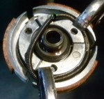
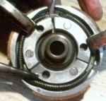
6. The circular coil spring is carefully stretched and maneuvered into position. See photos below.

Step 6a. Getting everything ready for the spring pre-loading (stretching).

At the gaps between the segments, the leaf springs have “cradles”. These cradles prevent the spring from wandering either way and coming off. When installing, always put the c-clamps or vise grips where you can almost get two of the three cradles. Never clamp onto the spring or the brake lining. Left, initially set the clamps like this. There’s no tension in the spring yet.

>

>

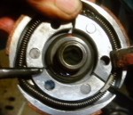
Step 6b. Gently stretch with soft thumbs then clamp it

Now with both your thumbs, gently stretch and lift the spring onto the ledge, but not yet over the cradle. You cannot let go or it will come off and maybe fly away. Hopefully you have a third needle nose vise grips within arms reach that is already adjusted and ready to clamp. Without letting the spring snap back and without taking too much time, clamp the third vise grips (a needle nose vice grips like shown here is best) to prevent the spring from flying off.

>

Step 6c. Gently pry the spring over the cradle with a small screwdriver

Just like putting a tire onto a rim, that last little bit is the most difficult. It’s very easy to damage the spring by forcing it to go when it doesn’t want to. If it gets tight, release and try to take a smaller bite. If the new spring is over stretched by rough handling during installation, it will be like having an old softer one.

>

>

7. Once it snaps over the cradle you got it. Now just push on it to snap it in it’s groove all around.

8. Place the assembled 1st speed clutch back on, tighten the nut with the impact.

9. Put the two rear shaft’s shim washers 10 & 16mm in place, clean the gasket surfaces and any sludge.

9a. For Pedal Models:  Take the left pedal crank off, or at least park the pedal in the down position. The weight of that far side pedal makes the pedal shaft point wrong, causing the transmission cover to not go on right.

9b. For Pedal Models: Make sure the U-shaped clip is in it’s slot in the case wall. The starter (pedal) shaft should move 45 degrees back and forth. If only the clutches were removed, and not the countershaft and pedal shaft assemblies, then it will still be in it’s slot, ready for the trans cover to go back on. More pictures of this will be put here soon …

10. Put the trans cover on. When everything is aligned, it makes a loud clap.

11. Then tighten the trans cover bolts. Put new ATF fluid and go try it out!


Carb Service and Jetting

October 26, 2008

Derbi Serviceman YellowWelcome to Myrons Carb Service and Jetting tutorial. As most of you know, the main function of a carburetor is to blend the gasoline with air to make an explosive mist of super fine droplets. In order to burn all of the oxygen and all of the gasoline, they must be in the right ratio, or else oxygen or gas will be left over, and wasted out the exhaust pipe. The carburetor also has a control valve, in most moped carburetors it is a slide type, that controls the power of the engine. When you want to accelerate, twisting the right handlebar grip towards you pulls a cable that pulls the throttle slide up. This “opens the throttle”, and lets the maximum amount of air get through. Moped and motorcycle carburetors also have a small reservoir of gasoline, called the float chamber or float bowl. An automatic valve attached to a float lets gasoline into the reservoir when the level gets too low, and shuts off the supply of gasoline when the level gets too high. The reservoir insures a fairly constant supply of gasoline, even when the demand changes as when the rider opens and closes the throttle. The float is operated by gravity, so when the bike is laid over on it’s side, and the fuel petcock is on, gas will leak out, either onto the ground, or into the air box and engine, or both. Always turn off the gas (fuel petcock at bottom of gas tank) before transporting the moped.


One or more jets
dip into the reservoir of gasoline. Suction from the engine draws gasoline up through the jets. The gasoline sprays out with fairly low pressure, like with a squeeze bottle sprayer with the trigger squeezed lightly. The pressure in the venturi is less than the pressure in the float chamber, which is at atmospheric pressure, thanks to one or more vents that allow air to escape from the float chamber when gasoline comes in, and to enter the float chamber when gasoline leaves. The biggest jet is the “main jet”. The size of the main jet is what determines the fuel and air mixture when the throttle is wide open. The other jets, needle jets, idle jet(s) or choke jet, matter only a little bit when the throttle is wide open, but matter a lot when the throttle is closed. On a Tomos A55, the idle jet is about 0.010″ (0.25mm) and the main is about 0.023″ (0.58mm), 2.5 times the diameter, and 6.4 times the area. So when the throttle is wide open, 86% (6.4/(6.4+1)) of the gasoline comes from the main jet and 14% (1.0/(6.4+1)) from the idle jet. Sometimes the “idle jet” is part of the carburetor bod
y and cannot be removed for cleaning or replacement. In those carbs, Peugeot Gurtner, Motobecane Gurtner, Delorto SHA, and others, there is a drilling procedure for cleaning, widening or relocating the idle passageway. In some there is no idle fuel passageway. Bing moped carbs use a channel in the bottom of the throttle slide to focus the air close to the fuel sprayer. Make the idle channel in the bottom of the throttle slide deeper, and the idle mixture will be richer. Make the idle channel shallower, and the idle mixture will be leaner.

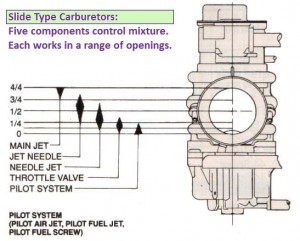
Slide Carburetors Diagram

What controls mixture depends on what throttle opening is:

Closed Throttle (Idle) Mixture is usually not adjustable, except by drilling or notching the bottom of the throttle slide. 

Mid-Throttle Mixture is governed by the needle and needle jet, if it has one. Puch & Sachs Bings do, Delorto SHA doesn’t.

Full Throttle Mixture is goverened by the main jet size. The number is, somtimes, the size in mm. So a size 50 jet is 0.5 mm.

Try not to confuse throttle position with engine rpm. “Mid range” can mean the middle of the RPM range, or it can mean the middle of the throttle range.

The main jet is always removable, and unscrews from the lower part of the carburetor since it is “underwater”. In most motorcycle carburetors the main jet is internal, where the float bowl must be removed (that usually means carb removal). In some moped carburetors, it is external, like Peugeot Gurtner, Batavus Encarwi, Tomos Encarwi, and Motobecane Gurtner. Those lucky moped owners can drain their float bowls by simply unscrewing the jet. The jet can also be cleaned or swapped out in under a minute.

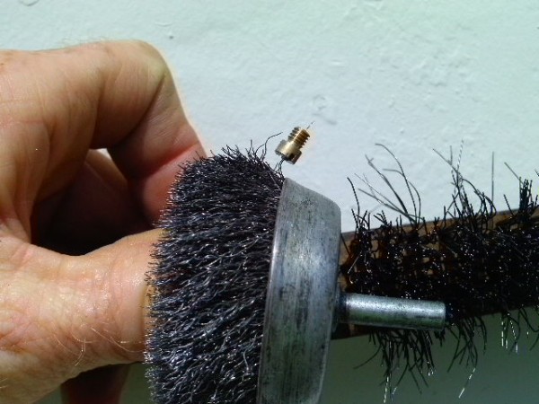
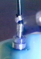
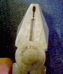
Above, a Tomos A55 idle jet (M4 thread) is physically bigger than a Puch Maxi main jet (M3.5 thread), but the hole size is much smaller. The photo shows how the #25 jet, 0.010″ (ten thousandths of an inch), will allow the thinner wire of the wire wheel to pass through the hole, but not the thicker wire of the wire brush. This is a useful cleaning technique.

With most stock moped engines, it’s easier to judge whether the jet is too big or too small, than it is with high performance two stroke engines, like dirt bikes. A stock moped with the correct jet will run smooth up to and a little beyond the engine rpm it is designed to max out at, and then, above that rpm, begin to “four stroke” or run rough. You want it to just barely not four stroke under most conditions.

If the jet is too big, the “four stroking” will begin too soon, before maximum speed is reached, and act as a brake.

If the jet is just right, the “four stroking” will begin a little above max speedgoing downhill or wide open stationary with the tire off the ground. If the top speed is 30mph, the four stroking should begin at 33-34mph. If the top speed is 35mph, the four stroking should begin at 38-39, and so on.

If the jet is too small, the “four stroking” will begin too late or not at all, even above top speed. Furthermore, if the jet is too small, power will fade out, without any roughness or stumbling, like a “waaaaaaah” sound, when the throttle is opened fully. This condition will cause excess heat, which can then damage the piston or worse. A little too hot is when the two stroke chrome exhaust header turns yellow. Way to hot, for a two stroke, is when the chrome turns blue, like a four stroke exhaust header often does.

Carburetor Replacement. When starting from “scratch” with a whole different carburetor or a different engine set up, the tuning books all say to start with a jet that’s too big and work down. Putting too big a carburetor will make it difficult or impossible to jet properly. When the carb is too big, you cannot make as much power at full throttle as you can at part throttle. There’s not enough suction from that little 50cc piston. Piston port kitted mopeds can benefit from big 20 to 24mm carbs. Reed valve 70cc kitted mopeds and non kitted 50cc sport motorcycles and scooters benefit from smaller carbs, 16 to 20mm. Smaller carbs start easier, idle better, they’re more fuel efficient, they take up less space and don’t stick out as much. The big carb might go a little faster but behave badly. 

Seat of the pants jetting is where you use a public street run the bike at maximum power for maybe 1/2 mile to 5 miles (eventually), listening to the sounds and feeling the forces made by the engine, to decide if the jet needs to be bigger or smaller. Each engine has it’s own personality. Some you easily hear the four stroking, and some you cannot hear it at all, but you can sort of feel it literally in the seat of your pants, like someone tapped the brakes. When the rough running mode begins the driving force suddenly drops, and you begin to loose speed. When the rough running ends and the smooth running begins, you suddenly feel a tiny surge of power, and your speed begins to increase. Seat of the pants jetting is also knowing the smell of “too hot” and how to judge how hot it gets by “reading” the spark plug. The hottest thing in the combustion chamber is the center part of the spark plug, the insulator, made out of white porcelain. On a normal spark plug there will be a light brown coating. On a hot running bike the same plug will be a lighter shade or almost white. On a cold running bike the same plug will be a darker shade of brown. Many other things also influence the spark plug insulator color, and can mask the effect of jetting, such as two-stroke oil mix type and ratio, old gas tank tar, compression leaks, spark plug heat range, and various engine modifications. For this reason a digital temp gauge is recommended. High tech jetting is done using full instrumentation like temperature sensors, exhaust oxygen sensors, in addition to a dynamometer. Graphs of engine rpm versus rear wheel driving force/torque/horsepower, are made for various jet sizes.  The jet that provides the most driving force yet still runs cool is the best choice. What is cool?  Below 300 degrees fahrenheit at the threads of the spark plug, after 30 minutes of hard running on a super hot day. What is hot? Above 350 degrees, also when fully hot. Having too much compression ratio (not enough combustion chamber volume) is a common source of excess heat in modified engines. So is too much ignition advance. Liquid cooled two stroke motorcycles run cooler, like under 250 degrees F. Cooler engine temperature makes more power because the crankcase can hold more weight of air since cooler is denser. That’s why all modern racing two stroke engines are liquid cooled, more power and longer life. Bigger cooling fins run cooler on air cooled, as do bigger radiators on water cooled. Moving fast through the air cools the engine. Going slow in the sand, or uphill with a heavy load on a hot day, overheats the engine. Because of all the many variables, jetting is often not easy. The bike must be otherwise in good working order and street legal, before the final jetting is done.

When just an exhaust is changed, from stock to aftermarket, usually the jet needs to be 1 or 2 sizes bigger. When the air box is removed the jet needs to be 2 or 3 sizes bigger. Some mopeds are missing their air box, and a replacement is not available. They must be jetted richer, or they’ll run hot and lose power when the throttle is wide open.

Sometimes the jetting can be adjusted by different air inlet tubes that plug into the air box. They are for noise reduction. The Delorto air boxes have two 1 inch by 3/8 inch plastic inlet tubes. When they are removed, and a bigger jet is installed, some more power is often gained, at the expense of more noise and less fuel economy. For example, a stock Garelli has a #50 jet with intake restrictors. Remove one of the two inlet tubes and it likes a #52 jet. remove the other and it likes a #54 or 56 jet. Speed might gain from 30 to 32 mph. Another example is the “snorkel tube” on the Puch Maxi stock air box. It should never be pushed up against the metal mesh air filter inside the air box, but rather be placed about a half inch away from the metal mesh, or else the air will be very blocked. Puch changed that design in the mid eighties and made it fool proof. Removing that accordian style inlet tube lets more air in, about equivalent to reducing the jet size by one or maybe a half step.  

When an engine that is jetted correctly for a low altitude is moved to a high altitude, like from sea level to 6,000 feet, the air is thinner, so the jet will need to be smaller by 1 or 2 sizes. At 8000 ft maybe two sizes smaller. The power output will be less.

When an engine has leaking crank seals it will need a bigger main jet and a much bigger idle jet, because some of the fresh charge will escape, while some fresh pure air will enter the crankcase, diluting the mixure. At lower rpms, due to momentum, the leak has more time to happen, so the engine will feel weak. At high rpms the weakness won’t be that bad. One trick is to cut a notch in the throttle slide to cause all the idle air to pass close to the idle hole where the gasoline sprays out. Notching the throttle slide enrichens the idle mixture to compensate for air leaks in the crankcase, and compression leaks in the piston and cylinder. The notch can be filled with epoxy to restore it, or the throttle slide can maybe be replaced, to undo the modification. If there’s an idle passageway, it can be made wider, by drilling, to make the idle mixture richer. A Delorto SHA idle hole is in the zinc body below the base of the vertical brass spray tube. It is stock about drill size 73. It’s common for an air-leaking older engine to benefit (idle better) by widening the Delorto SHA idle hole to drill size 71, and even all the way up to drill size 68. When the engine has low suction, the idle hole needs to be huge or else it won’t idle. The droplets then are bigger and the idle is rougher. It’s either that or it’s an expensive engine overhaul or new engine. 

 Carburetor Service

Wear eye protection. Read warnings. Carb spray is a strong solvent. It will damage paint and most plastics, as well as human flesh. Carb dip is also a mix of strong chemicals that will burn skin, cause blindness, or mess up your nice new paint job. Use caution. These procedures are not for everyone. Use your own judgement. Read and follow the warning labels. Use this at your own risk. It’s easy to do more harm than good.

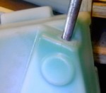
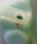
One little flake of this white crust became lodged in the float vent hole, causing this almost new Puch carburetor to leak gas, and to starve for gas, for no apparent reason.

One tiny flake of this white crust became lodged in the float chamber vent hole, causing this almost new Puch carburetor to leak gas, and also to starve for gas sometimes, for no apparent reason.

A quick clean is to remove the float bowl, keeping it vertical so as to not spill the gasoline it contains. If the carburetor has no been cleaned recently it might be all coated with brown or yellow varnish or white zinc oxide corrosion. If it is then a full clean is needed. If the carb is already clean inside, then inspect the gasoline for several possible contaminants. One tiny spec or fiber is all it takes to block a jet hole. See Gas Tank Cleaning section. Remove the jet and hold it up so your eye is looking through the tiny hole, with like a sunny white wall in the background. A normal jet will be wet with clear liquid that tranmits light. Blow air near it lighty with your mouth. Now the liquid will be gone. It should look like a solid white circle. A blocked jet will be black, and a flake or a fiber will make the hole look non-circular. Be aware of reflections from the brass walls. Clean out the jet, if it is blocked, with a piece of thin wire, like from a wire brush or the smallest guitar string. Better yet use a jet drill of a slightly smaller size, as a tiny round file, to scrape off the varnish from the inside of the hole. See the Bing or Delorto Jet Sizes Charts for drill numbers and jet numbers conversions.

A full clean is to disassemble the carburetor, separate out the rubber parts, and then soak the carb body and non-rubber parts in carb dip, or spray them with carb spray and maybe scrape the float bowl with a pocket knife or with steel wool. Polish the float seat with a spinning Q-tip on a drill. Clean out and test spray the passageways. Be careful not to spray it at your face. Look up the specific layout of your carb to know where any “secret” holes are at. Spraying up from where the main jet goes should cause spray to come out all available verturi holes, sometimes one, two, or three, depending on the carburetor.

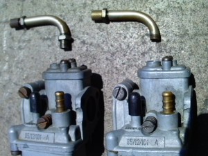
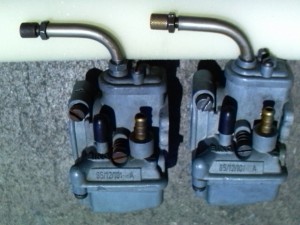
How to fix a broken “carb elbow”: The carb elbow is a curved metal tube that redirects the throttle cable at the top of the carburetor. Not all moped carburetors have a carb elbow. Instead they have linkage, like Peugeot 103 and Derbi DS50. Without a carb elbow, the throttle cable would go straight up, and interfere with your leg when you step through the frame to get on the bike. Without a carb elbow, the throttle cable would be different, since there’s length missing from the outer stationary part of the throttle cable. Some carb elbows have threads and screw into the top of the carburetor. Some don’t have threads and just rest in a hole in the carb top. The threaded kinds often get broken, usually by getting kicked. Fortunately, there’s an easy and free remedy.

Above left, unbroken and broken carb elbows removed. Above right, unbroken and broken carb elbows installed.

Usually it breaks at the bottom of the lock nut, leaving a few good threads where the lock nut was. Eliminate the lock nut and possibly file the broken edge if it sticks out. Then screw the broken carb elbow into the carb top, without any lock nut. Then turn the adjuster at the other end of the carb elbow, if it has one there, to take up the slack caused by the missing section of the carb elbow. Lube the throttle cable before reassembly.

How to fix a sticking throttle: Be aware this is a potentially dangerous condition. Don’t let anyone ride the bike until it’s fixed. Lube the throttle cable, and throttle sliding block, if it has one. Visually check the cable for kinks, or too many bends, or a crushed spot. Straighten out any kinks and remove excess cable ties. The cable should go as straight as possible, yet not hang out or dangle. If it hangs out it can get caught, and either kinked or crushed by the steering stop. Routing needs to be near the steering tube of the frame, so that when the steering is turned, it does not affect the throttle. Look at the original factory photos of mopeds in Myrons Moped Encyclopedia, to see how the throttle cable is supposed to go for your particular bike. It might not show it or say it all the way. If it still sticks try moving the throttle further out on the handlebar. Sometimes when a moped falls over, the throttle gets pushed inward, and rubs on the end of the handlebar. If that’s not it, then disconnect the throttle cable to isolate the throttle control from the throttle cable. Pull on the throttle cable with your fingertips or a small pliers. It should feel free and smooth, not rough or raspy, and snap back freely. Then twist the throttle control. It should also move completely free, like a wet ice cube on a smooth table. Replace the throttle cable with a modern kind with a slippery lining of nylon. Some throttles clamp onto the handlebar, and some have a cone shaped wedge that digs into the handlebar. After usually thousands of miles, a wedge type throttle might get loose because of erosion of the handlebar. Then tightening the wedge bolt can cause the throttle to stick because it becomes misaligned. The remedy is to replace the handlebar, or the free and easy option, reposition the throttle a little (1/2″) further out, on a fresh section of handlebar. Finally, sometimes when you change handlebars, the new bars might cause the throttle to stick, either because the throttle is misaligned by being positioned on the part of curved section, or the handlebar is too thick, like some powder coated ones are, and the thick paint needs to be sanded off where the throttle twist tube rubs against it. If you changed to low bars, without shortening the cables, it might be from the four extra 90 degree bends, where the cable has to turn up, u-turn over the top, and turn horizontal again at the bottom of the roller coaster. Sometimes throttle sticking is caused by too much grip glue. Sometimes it’s from a worn out sliding block. Allways lube cables and throttle first, and every so often, but not with WD40. Use oil, grease, or cable lube. Vegetable oil or Vasoline is better than WD40. WD40 is a penetrant and a Water Displacing agent. It’s great for the first time, because it gets in deep and fast, but doesn’t last long. Regular motor oil is better for follow up lubing.


to be continued … fuel leaks and remedies, troubleshooting with carb spray


Carburetor Replacement

Moped carburetors come in different sizes from 7mm to 14mm venturis, and from #39 to #68 main jets. A Puch carb might be a 14mm Bing with a 64 jet, while another Puch carb might be a 12mm Bing with a #60 jet. So there are different configurations. When you get a new carb, you generally have to re-configure it. That means learning about jetting. Final jet selection requires a safe, legal, operating bike that can run hard wide open. The engine temp is “sensed” or smelled or a digital temp gauge is used. Read more about that in Service.  The point is, it’s generally easier to repair the old carburetor, than to purchase and re-configure a new one. That said, many people put new Dellorto SHA14/12 or 15/15 carbs on older mopeds. They don’t leak but they’re not jetted right. Not all mopeds have the right intake pipe diameter. The carburetor must fit precisely. Getting the right adaptor sleeve is sometimes not possible. The various intake pipe clamp diameters are listed in the Dellorto SHA parts list. 

Myron Derbi Goodwrench wishes you a safe, happy and successful carb service.


Gas Tank Service

August 21, 2008

Welcome to Myrons Carburetor and Gas Tank Service Section. Carburetors and gas tanks get coated with sticky brown residue (tar, varnish, or gum) from gasoline and oil decomposing during years of storage. Steel gas tanks rust inside. Rust flakes damage gas valves (petcocks). Rust powder goes through fuel filters and clogs the tiny 0.010 to 0.025″ jet holes that the gasoline sprays through. Rust particles and fibers from cloth or hair can also make the float valve not shut off, causing a gas leak.

Carburetor Gas Leaks:  Most (but not all) gas leaks are from float valves not shutting off. A good working float and float valve assembly will float up and shut off the supply of gasoline before the level gets as high as the float bowl gasket. If the bike is standing up stationary, it would not matter whether it even had a bowl gasket. The float bowl gasket is for when the bike is leaned or the moved around, sloshing the gasoline inside.

How to Clean Gas Tanks

Warning: The following procedures are difficult and dangerous. You can easily harm your health, get blinded, or ruin the bike. Read all warning labels. Acetone especially is a very strong solvent. It’s the main ingredient of fingernail polish remover. It will instantly dissolve decal ink or spray paint. It will ruin rubber by making it swell up. It will etch (eat away the surface) paint and plastics quickly. Baked on factory paint takes a minute to be etched. Wear eye and skin protection and have cloth towels ready to catch any dribbles. Nothing else that’s safer than acetone or methyl ethyl ketone (MEK) will dissolve the tar. This is how Myrons Mopeds cleans gas tanks. These techniques may not be safe or appropriate for everyone. Use these prodedures at your own risk.

1. With the old gas still in it, shake up the gas tank. On a frame-tank moped, shake the entire bike by tipping it up on it’s nose (front tire), while holding the front brake, balancing the bike on it’s front wheel. This gets the solid material (rust flakes mostly) off the bottom and into the liquid about to be drained out. Do this just before removing the gas valve, so rust powder won’t have time to settle back to the bottom.

2. Remove the gas valve and drain the old gas out, with shaking. Look at what came out. Pure fresh gasoline is clear, colorless, and smells like gas. Fresh gas put into a tarry gas tank turns yellow after a few days. Yellow tint means tar is present. Cloudy means water is present. Solid brown, black, or orange particles or flakes are rust. Two-stroke oil is usually colored so it tints the gasoline, so you can tell how much oil is present by looking at it. A 50:1 mix of Champion tints the gas slightly green. Twice as much oil makes it twice as green.

3A. Cloudy only – water:  Air dry the tank. Compressed air and summer sun help. Optional: Acetone or MEK 8oz rinse removes water quickly, no waiting.

3B. Dark color only – oil: Replace gasoline with correct mix, usually 50:1. Adding oil reduces the odor of gasoline. Pure gas smells strongest.

3C. Particles only – rust: Water flush with full blast garden hose to float out any loose rust flakes. Put the hose in the empty tank first before turning it on. Tip the bike so the water overflows to the side and not all over the bike. When “all” of the tar and loose flakes are removed it’s ready for EvapoRust. It’s a water-based product that chemically disolves rust, while not promoting re-rusting. Between a pint and a quart of Evaporust plus a two quarts of water almost fills a one gallon tank. Soak it for a day while shaking it vigorously (turning it upside down) once in a while. Then drain it out. Hose it with water from a garden hose. Remove all water ASAP before new rust can form. Use air, sun, or acetone for that. See above.

3D. Yellow color – tar: Soak the tank with acetone. Acetone costs $16/gallon, so it’s wise to cut it to 1/2 acetone and 1/2 gasoline, called a “cocktail”. With the gas valve hole plugged add the cocktail. Let sit for a day or so, with occasional shaking. On a frame-tank moped, tip it up on it’s fron wheel every half hour for 12 hours, or equivalent. Drain it out into a pan, with shaking. Examine how yellow and how much rust. Repeat as necessary. This is much easier said than done.

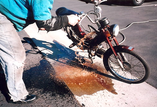
4. Additional techniques: A “whacker” is a 20″ piece of cable or a wire coat hangar spinning on a drill. It is useful for knocking rust flakes off the walls. A “chain” is a way of reaching to the far bottom, shaking or agitating vigorously, and then pulling it back out, thus stirring up the stew. A “pea light” is a tiny light small enough to pass through the 8mm gas valve hole, with stiff wires and a battery, for viewing the inside of the gas tank. You can sometimes see blobs of dark brown tar at the bottom, occasionally as big as a hand. A “geyser” is on a really bad tarry tank after a cocktail has soaked, you put a garden hose at the bottom of the tank, then turn it on full blast while tipping the bike away from you. The tar froth is lighter than water, and comes bursting out the open gas lid hole in a orange-brown geyser. The geyser gets the tar out the large top hole faster than repeated drainings out the tiny bottom hole. The geyser will make the ground orange colored and is not very environmentally friendly. Use your own judgement.

5. Professional Help: “Hot Tank” is what some radiator shops have to clean parts in.  Hot tank will ruin decals and paint. “Sand Blasting” is what some radiator and automotive shops have. It also damages the paint and can miss hard to reach places. Either way you would have to remove the tank (or strip the frame bare, if the frame is the tank).

6. Holes in tank: Rust can go all the way through the steel wall and form a blister under the exterior paint. Sometimes the act of cleaning the tank causes leaks, which were there already but not active. When you see little mounds, bumps, especially near the bottom, it means that the gas is held in only by the paint. A leak could happen anytime. Just poke one with a pointed steel “poker” like a large safety pin or a sharpened nail. A light push will pierce through. Fortunately epoxy will seal the hole, once the area is clean and free of paint. It’s better to pierce the hole besides cleaning it, so the epoxy will form a plug. Mix a 50/50 two-part epoxy for bonding metal like JB Weld or PC-7, not the clear kind.

What “rinse” means: On a frame-tank moped, “rinse” means first making a plug for the gas valve hole out of a bolt and a piece of fuel line, plugging the gas valve hole, adding the rinsing agent, which is acetone, tipping the bike up on it’s nose, sloshing the liquid violently to get the upper part of the tank, then setting the bike down, immediately pulling the plug off and draining out the rinse, while shaking the bike. Repeat the process until nothing bad comes out.

5. Not-frame Gas Tanks: If you can remove your gas tank from the frame, cleaning is much easier. Shaking it and seeing inside is easy. Pointed screws can be added to a mix of acetone and gasoline, then shaken vigorously. Dry wall screws are better than rocks because rocks leave sand grit behind.


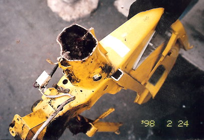
Left, a Motobecane tank, cut in half, is packed solid with tar. Right, a tank cleaning “geyser” of acetone, tar, and water.


Wiring Diagrams A to Z for thee!

August 20, 2008

Welcome. The wiring diagrams below come from 1) original owners manuals, 2) service manuals, 3) supplement sheets, 4) parts manuals, 5) actual mopeds, wirings, or parts, new or used, or most often 6) a combination of most of those. The manuals and sheets were in the wall of printed material from Myrons Mopeds buyouts of over 20 other moped shops. The raw originals were designed for black and white printing and copying, so they had the wire color names written in text. Myrons Mopeds has colorized them, and eliminated the color names, making them much easier to understand and follow. When needed, they have also been rearranged, scaled, and edited for clarity.     

A=====================

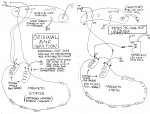
AMF Wiring: This wiring info is for the AMF Roadmaster models 110, 115, 120, 125 with McCullough rear friction drive engine, not the models 140, 141 with Minarelli V1 mid-engine and chain drive.
AMF CDI Ignition Upgrade
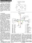
AMF 110,115,115KM
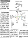
AMF 120, 125, 130
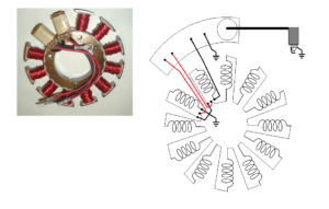
AMF 110 wiring
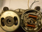


AMS has a Taigene Magneto

AMS motor, Sachs 505/1D
3-wire Taigene Magneto
90mm Bosch compatible
blue, blue/black, yellow
Honda points & puller tool
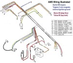
AMS Wiring Illustrated Sachs 505 Taigene 3-wire external ignition ground

AMS Wiring Illustrated
Sachs 505/1D engine
Taigene 3-wire magneto
external ignition ground


AMS Wiring: AMS Sierra 50 (step thru), Tahoe G1 (top tank) and Tahoe G2 (top tank 2 speed manual) have the same wiring as General 5 Star ST, except with a Taigene magneto, 3-wire with external ignition ground blue/black for battery charging, no ignition switch in the fork lock, and possibly minor differences in some connectors and grounds. Always ground the blue/black if there is no spark.  

The Taigene FP43 90mm 3-wire magneto is Bosch-compatible. Too bad it was prone to loose spark, even with the blue/black wire grounded and the points functioning. Some needed upgraded to an actual Bosch magneto.  

AMS & Angel Battery Versions: Angel/Speed Birds use a 6N2-2A small 6 volt battery, AMS uses a 6N4B-2A. Modern replacement batteries have different wires than the original ones did. See section “B” Battery Wires. 
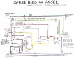


Angel Wiring Diagram

Angel Wiring 1) and 2)
Wtemco or Bosch 3-wire
external ignition ground

Angel: 1970’s Angel and Speed Bird mopeds, made in Taiwan by TYM, can have three different magnetos and two different wirings. These all have Ø90-three-M4-screw stator plates, and Ø90 (90mm ID) flywheel-rotors.

1) Bosch 0212-112-053, with brown (external ignition ground), yellow, black wires. The brown wire is the “tail” of the ignition source coil, and must always go to ground to have spark. It helps to power the headlight. So the headlight or headlight wires can cause the ignition to loose spark. 

2) Wtemco FHA ?????, with brown (external ignition ground), yellow, black wires. This whole magneto interchanges with Bosch 0212-112-053, but the internal coils are different. The flywheel, stator plate, points, condenser, the wire colors and wire plugs are all the same.

3) Wtemco FHA 11035, (internal ignition ground) with red, yellow, and black wires. This is the same as the other Wtemco magneto, except for the source coils (armatures). The headlight wiring is different from the others, in that the yellow does not get help from the ignition ground. This would make the headlight dimmer, but at the same time there is a separate output for battery charging, so the headlight gets brighter from that. The net effect is slightly dimmer.
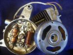
1) Bosch 0212-112-053
external ignition ground
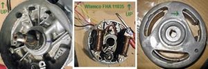
3) Wtemco FHA-11035, internal ignition ground
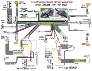


Avanti Supersport (top tank) Wiring

Avanti Supersport (top tank) Wiring
Seel 4-wire CDI magneto
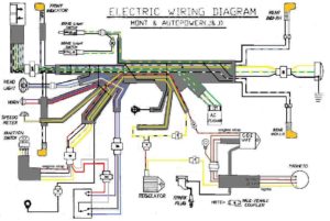
Avanti Autopower and Mont Wiring

Avanti Autopower and Avanti Mont Wiring
Garelli-clone engine, Seel 4-wire CDI magneto
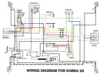


Avanti Kobra 3G Wiring Diagram

Avanti Kobra 3G
Garelli 2-speed clone
Seel 6-wire CDI magneto
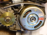
Avanti Autopower motor Seel 4-wire CDI magneto

Avanti Autopower motor
Seel 4-wire 50 watt CDI
magneto, made in India

Avanti Wiring: Early 2000’s Avanti mopeds have a 90mm 50W Seel magneto, made in India, with modern CDI electronic ignition. Mont and Autopower have 12VAC one-wire for all lights, with an electronic voltage (shunt) regulator. Kobra has 12VAC on 3 separate lighting wires, with no external regulator.

Avanti controls are copies of late 1980’s Italian made Domino controls, used on Trac, Tomos, Derbi. The switches are copies of late 1980’s Italian made CEV switches, that integrate (fit into) the mounts for the controls (brakes, start, and throttle). The switch buttons use the same white international icons, rather than words. 

The original switches for domestic (India) models did not have a handlebar mounted engine stop switch, reachable by the right thumb while holding handlebar grip. The older wiring diagram for Kobra shows this. Only the key on the dash would turn off the motor. But on at least the Supersport model, and maybe also on some Autopowers and Monts, they made the right side headlight high-low beam switch into a engine stop switch, in order to meet the US DOT requirement. This has been the source of confusion. (Turn on the high beam or it won’t start?)

These three wirings took 24 hours to interpret, colorize, re-draw and clean up. The originals were very rough.

B=====================

Batavus VA 76-78

Batavus VA, HS50
Mobat, Bronco, Starflite
without turn signals
1976-78, M48 engine
Bosch 5-wire magneto
internal ignition ground

Batavus VA, HS50 deluxe w/turn sigs 1976-78, M48 eng

Batavus VA, HS50
Mobat, Bronco, Starflite
deluxe w/turn signals
1976-78, M48 engine
Bosch 5-wire magneto
internal ignition ground
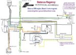
Batavus Regency wiring diagram

Batavus Regency Wiring
& Regency VA, 1978-80
Batavus M56 engine
Bosch 3-wire magneto
external ignition ground

Batavus Wiring (early): The 1976-78 models with Laura M48 engine have a 90mm Bosch 5-wire magneto on the right. Those have an internal ignition ground. None of the lights matter for the ignition to have spark. Head light (yellow), tail light (grey), and brake light (green) each have their own generator coils.


Batavus Wiring (late): The 1978-80 models with Laura M56 engine have a 80mm Bosch 3-wire magneto on the left side. Those have an external ignition ground. That blue/black wire powers the brake light. Consequently there is a special brake light resistor inside the light. While the early ULO 2-bulb tail light did not have a facility for holding a resistor, the later ULO 2-bulb tail light did. In fact there was not just a resistor, but a small circuit board with a nichrome-wire-coil resistor, and a diode. Otherwise the ignition looses spark if the blue/black becomes disconnected.  
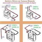
Battery Wire Versions Taiwan 6V Mopeds
Battery Wire Versions
Taiwan 6V Mopeds

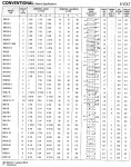
6 Volt Battery Chart 2008

6 Volt Battery Chart
by Yuasa (2008)

Battery Wires: For vintage Taiwan-made mopeds with 6 volt batteries, General, Lazer, Angel, Speed Bird, Indian, AMS, Clinton, Grycner, and others, getting the correct battery, 6N2-2A or 6N4B-2A is easier than getting the correct battery wires. In the 1980’s, new replacement batteries had vintage moped wires (double female bullet and male blade or bullet, male bullet). In the 1990’s and 2000’s the replacement battery wires changed, see illustration. In the 2010’s the wires changed again to “universal” (female bullet, female bullet plus an assortment of plug-in adapter wires, all bullet connectors). But the assortment does not contain enough to make vintage moped battery wires. To make those from the assortment, cutting, soldering, and shrink-wrapping is required.

Some vintage mopeds have had the bike’s wires adapted to accept a modern battery. Because of so many possible wires, since the 1990’s Myrons has always transferred the old battery wires onto the new battery, whenever the old wires were available. When unavailable, adapter wires were made, mostly from wire scraps. So many have been made, that almost no traces of the old style battery wires survive at Myrons Mopeds, out of hundreds of moped wire scraps.


Benelli Wiring: The Benelli G2 moped has a Dansi 3-wire 80mm magneto, with an external ignition ground on the green wire, ignition on the red wire, and lights on the black wire. The Benelli Dynamo mini motorcycle also has a Dansi magneto. More on Benelli soon …

Bianchi Wiring: Bianchi mopeds, US models with Morini MO1 engines, all have Dansi magneto type 101732. This magneto is essentially the same as the 101765 3-wire 2-coil, with external ignition ground on the green wire. Ground the green wire to get spark before suspecting anything else. 

C=====================

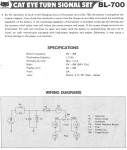
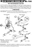
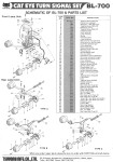
Cateye Turn Signals: Cateye turn signal kits, made in Japan, were an add-on accessory. They had a rechargeable 5.5 volt Ni-Cad battery pack, mounted with the front two lights on a chrome bar that clamped onto a moped handlebar. All of those original batteries died in the early 1990’s.
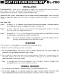
Cat Eye Turn Signals 1

Cat Eye BL700
Turn Signal Set p1

Cat Eye BL700 Turn Signal Set p2
Cat Eye BL700
Turn Signal Set p2

Cat Eye BL700 Turn Signal Set p3

Cat Eye BL700
Turn Signals p3

Cat Eye BL700 Turn Signals p4
Cat Eye BL700
Turn Signals p4


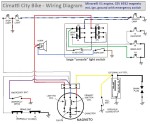
Cimatti City Bike Wiring

Cimatti City Bike Wiring
CEV 3-wire magneto
external ignition ground
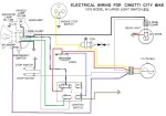
Cimatti City Bike Wiring for model with large console light switch

Cimatti City Bike with large console light switch
CEV 3-wire magneto
external ignition ground

Concord Wiring
1980 Freedom , Invader
CEV 3-wire magneto external ignition ground


Cimatti Wiring: Cimatti, with the Minarelli V1 engine,  has functionally the same as the “Minarelli Wiring”, except for the high-low beam headlight, the console light/horn switch, and the secret toggle switch under the headlight that grounds the blue wire when in the forward position. 


Concord (Fantic) Wiring: Concord mopeds with Minarelli V1 engines have “Minarelli Wiring”. The ignition source ground powers the brake light and must be grounded to run. There is a secret resistor inside the tail light. When that burns out the engine dies when the brakes are applied.
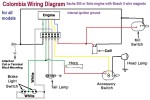
Colombia Wiring Diagram
for all moped models
Sachs 505 or Solo engine
Bosch 5-wire magneto
internal ignition ground

Colombia Wiring: American-made Colombia mopeds can have two different frames, mono-tube and stamped sheet, and two different engines, Sachs 505 or Solo belt drive. But they all have the same Bosch 5-wire 90mm magneto, same wiring and electrical equipment, except for the headlight. Blue is ignition, green and green/black are brake light, yellow is head light, and grey is tail light. 

Invisible Forces: Notice that on the Colombia (and others) the tail light gray wire goes straight from the generator/magneto to the light, and not through the light switch. You would think the tail light would then stay on all the time. The small tail light generating coil is close to the larger head light generating coil. Somehow the magnetic field changes around the head light coil when the light is switched on, and that energizes the nearby tail light coil. So the tail light only works when the head light is working. This prevents tail light burn out caused by overload from a burned out headlight. On other 70’s mopeds, when their head light burns out, the tail light gets super bright, and dies.

Furthermore on mopeds with a Bosch 90mm magneto with grey tail light wire, such as Puch, Batavus, Colombia, the headlight bulb is preferably a 6 volt 21 watt (#1129). If it’s a 12 volt 21 watt (#1156), the headlight won’t be as bright, and since it passes less current, the tail light won’t be as bright either. That’s weird. Besides that the tail light bulb needs to be a 6 volt 5 watt #63, or else it will be dim, especially at idle.

D=====================

Daelim Wiring: Daelim Motor Corp (DMC) made Trac mopeds for the US in the 1980’s. See Trac Wiring.
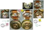
Dansi magnetos

Dansi Magneto: These 3-wire magnetos are used on Benelli, Morini and Rizzato moped engines. Dansi magnetos are included here in wirings because of the number that is stamped onto the 80mm ID flywheel. That number determines the brake light wiring, brake light switches, and tail/brake light type, and more importantly, whether or not it has a “secret” wire that needs to be grounded. Dansi 101286 (anti-clockwise) and 101441 (clockwise) wires are: red = ignition, black = lights, green = brake light. Dansi 101765 (anti-clockwise) and 101732 (anti-clockwise?) wires are: red = ignition, black = lights, green = ignition ground (brake light). If you have an external ignition ground type 101765 or 101732, always ground the green wire first, when checking for spark. See Morini Wiring.  
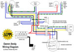
 

Demm Smily wiring diagram

Demm Smily

Demm Wiring: Demm Smily, US models 1976-78 have Demm one-speed engines with CEV 6933 magnetos. The blue magneto wire is an ignition ground that also powers the brake light.


Derbi Wiring: Derbi mopeds, US models 1976-1989, except the DS50, have Motoplat 3-wire magnetos with points, and an external ignition ground on the blue wire powering the brake light. Inside the tail/brake light is a secret hidden ignition ground resistor. If that goes bad, or the wire leading to it, the ignition will loose spark when the brakes are applied. If any of the brake switch wires are also disconnected, then there will no spark all the time. The front ignition ground junction is on the right headlight mount, which is floating in rubber. The rear ignition ground is on the left rear fender bolt, underneath. Both of those places get corroded or loose. Ground the blue wire from the engine first, when checking for spark. Then all those rusty loose grounds don’t matter. That disables the brake light, for emergency or troubleshooting.
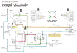
Derbi Variant 1976-86
SL, SLE, RD50, Laguna
Motoplat 3-wire magneto
external ignition ground
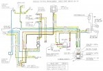
Derbi Variant Sport

Derbi Variant Sport 86-89
6V AC voltage regulator
Motoplat 3-wire magneto
external ignition ground
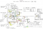
Derbi Variant Sport 1986-89

Derbi Variant Sport 86-89
6V AC voltage regulator
Motoplat 3-wire magneto
external ignition ground
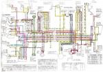
Derbi DS50 1987-89

Derbi DS50 1987-89
scooter has floor & pedals
12V AC voltage regulator
Motoplat CDI magneto
also with electric start


E=====================

Eagle Wiring Diagram

Eagle I, II, and III Wiring
Bosch 3-wire magneto
external ignition ground

Eagle Wiring: Eagle mopeds were made by Hercules in about 1980-82. Eagle I and II are Sachs Suburbans (I has spoke wheels, II has mags), and Eagle III is a Sachs Prima G3 (top tank). They have a Sachs 505 one speed engine (1D for 30mph, 1A for 25mph, 1B for 20mph) with a Bosch 3-wire magneto, external ignition ground. Always ground the blue black magneto wire first if there is no spark. See Sachs Wiring for a way better version of this wiring diagram.


F=====================

Foxi Wiring: There are actually four Foxi moped models, each made in a different country, and each with a different wiring. 1) Sparta Foxi, made in Holland, see Sparta Wiring. 2) KTM Foxi, made in Germany, see KTM Wiring. 3) Testi Foxi, made in Italy, see Minarelli Wiring. 4) Jui Li Foxi, made in Taiwan, see General Wiring.  
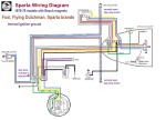
Sparta (with Bosch magneto) 1976-78 models Bosch 4-wire magneto internal ignition ground
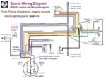
Sparta Foxi, F Dutchman 
’76-78 (made by Sparta)
Bosch 4-wire magneto
internal ignition ground

Sparta Flying Dutchman
’78-81 (made by Sparta)
Motoplat 3-wire magneto
external ignition ground
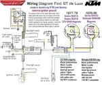
Foxi/KTM (US model) CEV or Motoplat magneto external ignition ground

KTM Foxi (US model)
CEV or Motoplat magneto
external ignition ground
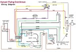
Flying Dutchman (Kynast) Wiring Diagram

Kynast Flying Dutchman
(made by Kynast)
Bosch 4-wire magneto
internal ignition ground


Flying Dutchman Wiring: There are two models, Kynast (Germany) and Sparta (Holland). See also those names for more info. 

Free Spirit Wiring: The Free Spirit line was sold by Sears department stores in 1978-81. They did not say Sears anywhere on the bike. In fact there are no brand markings or names anywhere, except the ID plate and the back of the seat, that says “Free Spirit”. See Sears Free Spirit Wiring.

G=====================

Garelli Wiring Diagrams: All have CEV 3-wire magnetos with external ignition ground powering the brake light. Garelli wiring is functionally the same as “Minarelli” Wiring on many Italian mopeds. Only some of the wire colors and connector or switch styles are different.

Garelli mopeds US models 1976-86

Garelli Wiring Simplified
US models 1976-86
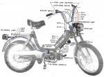
Garelli Wiring Actual
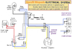
Garelli Wiring Actual

Garelli Wiring Diagram
CEV 3-wire magneto
external ign. ground 


1970’s Garelli Eureka and Katia (UK models)


General Wiring Diagrams: There has been confusion for years, because of 1) mistakes in the original wirings,  2) wiring in some models not agreeing with the original owners manual, 3) different brand names and alias names for the Jui Li, Her Chee, or Tsing Hua made mopeds, 4) lack of coverage of wiring issues in the service manuals (perhaps because different engines were optional, the engine manuals were separate and not integrated into the main manual), and 5) different versions were produced, sometimes without documentation. The wirings below come from actual wiring harness replacement parts, or actual mopeds or scraps of them. Showing the real wires alongside the diagram for them proves that these corrected wirings are accurate, even though some things might contradict some original wiring diagrams.  
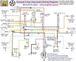
General 5-Star Wiring (top tank, Minarelli eng)

General 5-Star Wiring
top tank Minarelli V1 eng
CEV 3-wire magneto
external ignition ground 
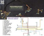
General Wiring Harness (top tank Minarelli eng)

General Wiring Harness
top tank Minarelli engine
CEV 3-wire magneto
external ignition ground 
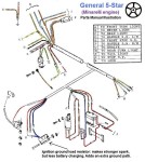
General 5-Star Actual (top tank Minarelli eng)

General 5-Star Actual
(top tank Minarelli) 

General Wiring Versions top - male battery wire bottom-fem battery wire

General 5-Star Versions
   battery wire, pink circle
top – male bullet
bottom-female bullet


General Brake Light Switches: General 5 Star (top tank) has the brake light switches that screw into the levers. General 5 Star ST (step thru) has a front brake light switch in the cable, and a foot brake switch. Other kinds (Lazer?) have both front and rear brake light switches built into the cables. Some of the wirings have an unused female bullet connector on the white wire, to allow either kind of brake light switch.

General and Lazer (Jui Li) top tank mopeds (Minarelli V1 engine with CEV 6932 magneto with external ignition ground): General 5-Star and Lazer Sport 50 have 97% the same wiring, except for: 1) General has a steering lock key switch, that kills the spark and un-grounds the battery when the key is removed, 2) Lazer has an additional lite green and red ground wire in the harness, 3) Lazer has a 6N2-2A battery, while General has a 6N4B-2A battery, twice the amp-hours and wider. 
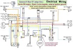
General 5 Star ST early

General 5 Star “early”
Sachs 505 foot brake
Bosch 3-wire magneto
external ignition ground
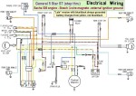
General 5 Star ST late Wiring

General 5 Star “late”
 Sachs 505 foot brake
Bosch 3-wire magneto
ext ign gnd (always gnd)
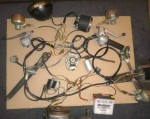
General 5 Star ST Actual

General ST “late” Actual
Sachs 505/1A foot brake
Bosch 3-wire magneto
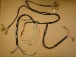
General-compatible Wiring new, unknown origin

General-compatible
new, unknown origin
for Bosch 3-wire magneto


General 5 Star ST step thru mopeds (Sachs 505 engine), made by Jui Li: General 5-Star ST wiring “early” version is functionally the same as the top tank models, because of the 3-wire Bosch magneto, configured to charge the battery from the ignition ground. With this version, if you removed the battery, or it went bad from sitting, the ignition would loose spark. The General 5-Star ST wiring “late” version instead charges the battery from the main lights wire and has the ignition ground always grounded, so it never looses spark even when the battery is removed. The trade-off for that increase in reliability is a slightly dimmer headlight, which is also a good thing because it helps prevent headlight burn out.
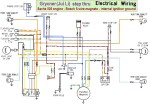
Grycner Wiring Diagram step thru with Sachs 505

Grycner Wiring Diagram
Sachs 505/1A engine
Bosch 5-wire magneto
internal ignition ground

AMS Wiring Illustrated Sachs 505/1D engine Taigene 3-wire magneto external ignition ground

AMS Wiring Illustrated
Sachs 505/1D engine
Taigene 3-wire magneto
external ignition ground

General look alikes:

Grycner mopeds are identical to General step thru, but have Bosch 5-wire magnetos, with internal ignition ground, and slightly different wiring. 

Unbranded generic Jui Li step thru and top tank mopeds are identical to General. Their wiring and magneto is unknown.

AMS Sierra 50 step thru and Tahoe 50 top tank, are made by Her Chee, not Jui Li. They have wiring compatible with General ST, and a Bosch-compatible 3-wire 90mm Taigene magneto. AMS has the later Sachs 505/1D rather than 505/1A.


General Battery Versions: All Generals and Grycners use a 6N4B-2A flat 6 volt battery. Notice in the “General 5 Star Versions” photo above how the original top tank wiring came with different battery wire connectors, either male or female bullet. Besides that the modern replacement batteries have different wires than the original batteries did. See above section “B” about Battery Wires.
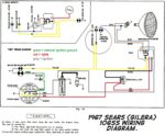
 

Sears (Gilera) 106 SS

Gilera 106 SS (1967) Sears Allstate (US model) has a CEV 6826 3-wire points magneto with external ignition ground on the green wire. If that wire is disconnected there will be no spark.


H=====================
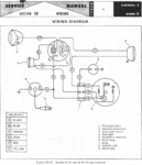
 

Harley D. M50, M65

Harley Davidson Wiring: 1965-66 Harley Davidson M50, MS50 models have Dansi ASL222S magnetos. 1967-72 M65, ML65, ML65 Leggero models have a Dansi ASL236NS magnetos. They all have 3 magneto wires, black (ignition), green (ignition ground and brake light) and red (lights). Red and black are opposite from most other Dansi magnetos. Green must be grounded (connected to the frame) in order to have spark. It powers the brake light. If the brake light burns out, the engine will loose spark when the brakes are applied. Any other situation where green to ground is interrupted will cause loss of spark, like wires under the rear fender cut by the tire, loose or rusted fender mounts, loose or rusted bulb contacts, or the tail/brake light connectors loose or corroded. Always ground the green engine wire to eliminate those causes of no spark. That allows the engine to run, but without a brake light. 

Hercules Wiring: Hercules mopeds, made in Germany, are also known as Sachs. See Sachs.

Honda Wiring: Honda has hundreds of small motorcycle models worldwide, with different wirings. These are the USA models (unless stated otherwise) of mopeds and motor-driven cycles. More to follow…
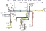
Honda C100 (50cc)

Honda C100 Cub series
CA100, C102, C105,
C105T, C110, CA110T
50 & 55cc 1959-70
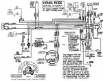
Honda PC50 (US model)

Honda PC50 (US model)

Honda PA50 Hobbit
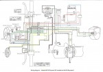
Honda PA50 Hobbit


Honda NC50 (US) Express Honda NA50 Express II
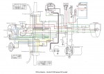
Honda NC50 (US) Express
Honda NA50 Express II

Honda NC50 (UK model)

Honda NC50 (UK model)


I=====================

Indian AMI-50 Wiring: Indian AMI-50 was made in Taiwan by Merida or Mira.

Indian AMI-50 Battery Versions: All Indians use a 6N2-2A small 6 volt battery. Modern replacement batteries have different wires than the original batteries did. See section “B” about Battery Wires.

Indian 1978 Wiring
WTEMCO 3-wire magneto
no key switch,
internal ignition ground

Indian Wiring 1979-84
WTEMCO 3-wire magneto
brake switches normally open, in parallel,
internal ignition ground


Indian 2-coil Magneto

Indian 2-coil Magneto
is actually 3 coil, since
2 are combined into 1
blue=ign, yellow=lites
green=battery charging

Indian 4-coil Magneto

Indian 4-coil Magneto
early models 1978?
2 small battery charge coils are in series, to
make the same 3 outputs

Indian Magneto Testing

Indian Magneto Testing


Indian ME100 Wiring:
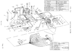
1973 Indian ME100


Intramotor Gloria Wiring: Of the 3 or 4 Intramotor Gloria models, Scout, Blanco, Kid and Mini-Kid, only the Scout wiring is shown. The others may or may not be the same, depending on their Dansi magneto type. See “Morini Wiring”.

Notice how the Euro model version has no brake light, and one clamp-on switch for lights, horn, and engine stop. Simple!
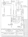
Intramotor Gloria Scout (USA) Schema Elettrico

Intramotor Gloria
Schema Elettrico
Dansi 3-wire mag.
internal ign. gnd
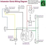
Intramotor Gloria Scout (USA) Wiring Diagram

Intramotor Scout
(USA) with brake light
Dansi 3-wire magneto
internal ignition ground
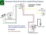
Intramotor Gloria Scout (Euro model) no brake light

Intramotor Scout
(Euro) no brake lite
one switch for all
Bosch 2-wire+spark
internal ignition ground


J=====================
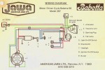
Jawa Babetta 1976-77 US model 207-011 4-wire star magneto with internal rotor Tranzimo CDI/coil

Jawa Babetta 1976-78
model 207.011 (0.9hp)
up to frame # 210999
4-wire internal rotor mag
big red Tranzimo unit
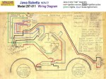
Jawa Babetta 1976-77 Diag. by California Moped

Jawa Babetta 1976-78
diag. by California Moped
model 207.011 (0.9hp)
4-wire int. rotor magneto
big red Tranzimo unit

Jawa Wiring: The original Jawa Babetta, with the famous red “Tranzimo” ignition unit (coil with electronic circuit) had 19″ rims was sold in Europe since 1972. Sometime after that the rims became 16″, and the model became also known as the “207”. Starting in 1976, American Jawa sold US versions of the model 207. They had brake lights and engine stop switches. The earliest US Jawa Babetta was the 1976-78 model 207-011, with big red Tranzimo ignition unit visible on the right side above the engine, with it’s high tech thyristor exposed on one end.


In 1978, starting with frame number 211000, the official US model name changed from Babetta to 50 DL, the model number changed from 207.011 to 207.111, and more importantly, the “big red Tranzimo” thyristor ignition unit and stator changed to the newer “black box with separate metal-can-coil” thyristor ignition unit and stator.
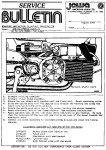
Jawa Service Bulletin Aug 1981

Jawa Aug 1981
Service Bulletin 1
On pre-’79 Jawa,
replace Tranzimo
and stator assy.
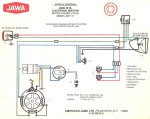
Jawa 50 DL 1978-79 US model 207-111 4-wire int rotor mag black box CDI unit metal can-type coil

Jawa 50 DL 1978
model 207.111 (0.9hp)
frame 211000 to 249999
4-wire int. rotor magneto
black box thyristor unit
metal can-type spark coil
no eng stop switch shown

Jawa Wiring Diagram no turn signals model

Jawa 50 DL 1978-79
no turn signals model
model 207.111 (0.9hp)
frame 211000 to 249999
4-wire int. rotor magneto
black box + metal can
revised w/ eng stop switch some revised wire colors
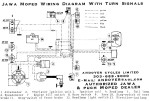
Jawa Wiring Diagram for turn signal model

Jawa 50 DLX 1978-79
deluxe with turn signals
model 207.111 (0.9hp)
frame 211000 to 249999
4-wire int. rotor magneto
black box + metal can


Jawa 50 DL 1979-80 model 207.311 C (1.5hp) model 207.311 DL (1.5hp) model 207.300 DLX (1.5hp) frame 250000 and up

Jawa 50 1979-80
207.311 C,DL,DLX
250000 – 349999
same wiring
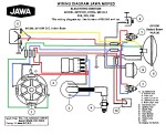
Jawa 50 DL 1979-80 207.311 C, DL (1.5hp) 207.300 DLX (1.5hp) frame 250000-up

Jawa mopeds 1980-82
207.311 50C,DL 207.300 50 DLX, X20,X25,X30
frame no. 350000-up
4-wire int. rotor magneto
no head light switch
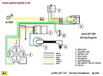
Jawa 207 Wiring Diagram no turn signals model

Jawa moped 207.305
no brake light (Euro)
no engine stop switch

In 1979, starting with frame number 250000, the USA models changed to the 207.300 series. The horsepower went up from 0.9 to 1.5. The carburetor changed from Jikov 9mm to Bing 12mm. But the wiring and electrical equipment stayed the same. 

In 1980-81, they had new model names, Jawa X30 (30mph 2hp?), X25 (25mph 1.5hp) and X20 (20 mph 1hp). The wiring did not change, but the tail light changed from Peterson to CEV.   

In August 1981, American Jawa sent out it’s first service bulletin, telling dealers how to cure the Tranzimo ignition problems once and for all, by replacing with the newer black box thyristor type.

In 1983, an all-new model was indroduced, the Jawa 210. It had a two-speed instead of one speed transmission. It had a new frame and other improvements. In the mid 1980’s the 210 was made in sport and deluxe versions. The wiring did not change on the 210 models for the rest of the 1980’s.

In the late 1980’s, Jawa made models 225 (25mph), 230 (30mph), 230 Breeze (30mph mag wheels). They had 2-speed transmissions, and some minor wiring differences.   
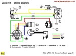
Jawa 210 Wiring no turn signals model

Jawa mopeds 1983-91
210 series (2-speed)
no brake light (Euro)
no turn signals
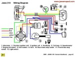
Jawa 210 Wiring for turn signal model

Jawa mopeds 1983-91
210 series (2-speed)
with brake light (USA)
with CEV turn signals
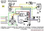
Jawa mopeds 1985-91 225/230 series (2-spd)

Jawa mopeds 1985-91
225/230 series (2-spd)
with brake light (USA)
no turn signals

Jawa Thyristor: Here is an excellent article on how to replace a burned out Jawa “black box”. There are just three components to buy and solder together, a thyristor, a capacitor, and a diode. Here is an even better article that shows in detail the ignition versions, upgrades, and individual thyristor component replacement options.  


In 1993, the country of Czechoslovakia split into Czech Republic and Slovakia. That was pretty much the end of the old Jawa. Then in the mid 1990’s, Jawa mopeds were re-made in Hungary at the Korado factory. The step thru models were called Babetta, while USA top tank models were called Jawa (1995 Sport, Supersport, Ultrasport). The re-make Jawa/Babetta wiring changed, to be like the 1995 Puch Korado, made in Hungary by Manet, with one wire for all lights and a 12VAC shunt type voltage regulator. See Manet Wiring for that. The last year for the beloved Babetta was 1997. Click here for the full Jawa history.

JC Penney Wiring: JC Penney department stores sold the Pinto and Swinger moped models, made by Kromag. They have Puch engines and 1977-78 Puch (6-wire) wiring, where the blue black horn wire must be grounded to run. See Kromag Wiring.

K=====================
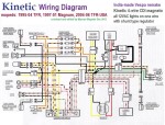
Kinetic TFR moped and Magnum, TFR-USA 1980's Vespa remake 4-wire CDI magneto

Kinetic (moped) Wiring 
India-re-make of a Vespa
4-wire CDI magneto

Kinetic Wiring: Kinetic TFR, Luna TFR, Magnum, and TFR-USA are modern 1990’s-2000’s remakes of a 1970’s-80’s Italian made Vespa(Piaggio) pedal-start mopeds. They have modern electrical wiring, with all lights on one wire and a shunt type voltage regulator. So there is no battery, and no DC anywhere, only 12 volt alternating current. They have modern CDI ignition, no points. The Kinetic Pride is a scooter (with a floor and no pedals) with a battery, electric start, and a different wiring, not shown here.

Korado Wiring: The Korado is a Puch re-make, made by Manet. See Manet Wiring.
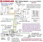


Kreidler MP9 (early) up to frame 2409540 Bosch 3-wire magneto external ignition ground

Kreidler Flory MP9(early)
up to frame 2409540
Bosch 3-wire 2-coil mag
external ignition ground
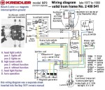
Kreidler MP9 (late) from frame 2409541 Bosch 3-wire magneto internal ignition ground

Kreidler Flory MP9 (late)
from about late 1977-on
frame 2409541 and up
Bosch 3-wire 3-coil mag
internal ignition ground
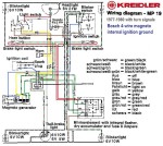
Kreidler MP19 Wiring turn signals & mag whls Bosch 4-wire 3-coil mag internal ignition ground

Kreidler Flory MP19
turn signals & mag whls
Bosch 4-wire 3-coil mag
internal ignition ground

Kreidler Wiring: These wirings appeared only in the Kreidler owners manuals, in tiny unreadable print. Now they are deciphered and made easy to follow. Even the mysterious diodes are explained. These 3 took 14 hours to scan in and fix up. Because the US requires a brake light, and requires that the head light not get dim when the brake light is on, that is why they used diodes, for bright lights with less bulb burnout.
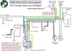


Kromag/Sears Wiring Sears Free Spirit, uses Puch 1977-78 (6-wire) 6-wire Bosch magneto 1-speed 0212 124 043

Kromag/Sears Wiring
Sears Free Spirit (1-spd)
Puch 1977-78 (6-wire)
external ignition ground

Green/black wire explained: Many Bosch magnetos have a green and black wire that simply goes to ground. Did you ever wonder why they did not just ground it internally? The Kreidler Flory MP19 is one moped that uses the grün/schwarz wire the way Bosch intended it. The green and green/black are inputs to a full wave rectifier, which is the four diodes inside the turn signal power pack. It is for battery charging. If the green black were grounded, it would only be a half wave rectifier, and the battery charging would only be half as much.

Kromag Wiring: Kromag makes the Sears Free Spirit moped line. All Free Spirits have the same wiring and electrical equipment as 1977-78 Puch Maxi (6-wire). The blue/black horn wires need to be connected, or grounded in order to have spark. The external ignition ground is through the clamp of the light/horn switch. Wild!


Kynast Flying Dutchman Wiring Diagram

Kynast Flying Dutchman
Sachs 504/1A or 508/AD 
4-wire Bosch magneto
internal ignition ground

KTM (US model Foxi) CEV or Motoplat magneto external ignition ground

KTM (US model Foxi)
CEV or Motoplat magneto
external ignition ground

KTM (Foxi) Wiring: This wiring is functionally identical to Cimatti, with a hi-lo headlight, console type light and horn switch, external ignition ground running the brake light, and a secret toggle switch under the headlight. When that switch is in the forward position, the blue (external ignition ground) wire is grounded, and the engine will run, even with a burned out or disconnected brake light. When the switch is in the rear position, the brake light operates normally, where the engine dies when the bulb is removed and either brake is squeezed.  KTM Foxi mopeds have CEV 3-wire magnetos. Some of the later ones with 504/1D engines have Motoplat 3-wire magnetos.

L=====================
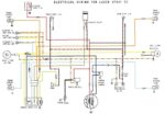
Lazer Sport 50 Wiring
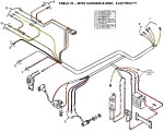
Lazer Wiring Actual
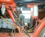
Lazer Wiring Actual

Lazer Wiring Battery

Lazer Wiring – battery

Lazer Sport 50 and General 5-Star have the same wiring, except for: 1) General has a steering lock key switch, that kills the spark and ungrounds the battery when the key is removed, 2) Lazer has an extra lt green/red ground wire, 3) Lazer battery is the smaller 6N2-2A, not 6N4B-2A. 

These wirings are for the 1977 Lazer Sport 50, orange, top tank moped, made in Taiwan by Jui Li. They are not for the 2000’s Lazer 4-stroke mopeds, made in China by Bashan. That is a completely different “Lazer”. 

Lazer Battery Versions: All Lazers use a 6N2-2A small 6 volt battery. Modern replacement batteries have different wires than the original batteries did. See section “B” about Battery Wires.

M=====================
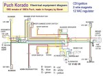
Manet-Puch Korado 1995 made by Manet

Manet-Puch Korado
remake of ’86 Puch 1-sp
all lights 1 wire 12VAC
2-wire CDI magneto

Manet Wiring: This is a mid to late 1990’s Puch remake, made in Hungary by Manet. It is better known as the “Puch Korado”. Some things, like the engine, are the same as Puch, but the electrical and wiring is all different. Like all the other all-AC modern (1990’s and later) mopeds, the Korado has all the lights on one wire, with a 12VAC shunt-type voltage regulator. Like everything modern, it has a completely separate and independent CDI (capacitor discharge ignition) system that in no way depends on the lights. The CDI has no pulser coil.

Manet/Korado also made the mid-to-late-1990’s Jawa remake. The wiring for that not currently available, but is expected to be close to this wiring and electrical equipment. 
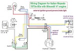


Minarelli Wiring Diagram for Testi/Gitane & others

Minarelli Wiring Diagram
for Testi/Gitane & others

Minarelli Wiring: Most Italian mopeds, US models, that have Minarelli engines have this same wiring, functionally. Many have the same exact colors as well. There are at least 21 names: Aspes, Baretta, Bianchi, Cimatti, Concord, Fantic, Gadabout, Gitane, Intramotor, Lem, Maico, Motomarina, Motron, Pryer, Red Foxi, Safari, Silver Foxi, Snark, Testi, Yankee Peddler, and others. They all have the Minarelli V1 or V1L engine with CEV 6932 3-wire magneto with external ignition ground (blue wire) powering the brake light. Ground the blue wire first if there is no spark.


Morini Wiring Diagram

Morini Wiring Diagram

Morini Wiring: Franco Morini moped engines can have two possible Dansi magnetos. Which one it has is determined by a number stamped on the flywheel. Some Italian mopeds, US models, that have Morini engines have this same exact wiring. This “universal” wiring can be configured for either NC-in-series (for Dansi 101765 or 101732), or NO-in-parallel (for Dansi 101286 magneto) brake light switches. Most others wirings are functionally the same as one of these two versions. There are dozens of brand names: Arciero, Benvenuti, Bianchi, Colt, Cosmo, F. Morini (no relation to Franco Morini), Intramotor, Italjet, Italvelo, Italtelai, Lem, Malaguti, Motomarina, Motobecane, Negrini, Pacer, Snark, Velomec, West Wind, and others. Morini is only the engine name.  

Dansi magneto 101286 3-wire 2-coil

has normally open brake light switches in parallel and an internal ignition ground.

Dansi magnetos 101765 and 101732 3-wire 3-coil

have normally closed brake light switches in series and an external ignition ground that powers the brake light.
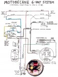
 

Motobecane 6V Models 1974-1977 2-coil mag

Motobecane 6V
1974-77 2-coil mag
3-wire Novi mag
external ign. gnd
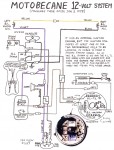
Motobecane 12V 1978-80 3 coil mag

Motobecane 12V
1978-80 3 coil mag
3-wire Novi mag
internal ign. gnd

Motobecane Wiring: Two versions for USA model mopeds.

Early “6 volt” version: Before Jan 1978, Motobecane mopeds had a 2-coil Novi magneto, with an external ignition ground. The ignition assisted in keeping the lights bright, in a complex way.

Later “12 volt” version: After Jan 1978, Motobecane mopeds had a 3-coil Novi magneto, with an internal ignition ground. However, the ignition coil still needs at least one of the two neighboring lighting coils to be active. Amazingly, the lights not working can make it loose spark, even though they are not connected. It has to be from the magnetic field. The wiring is also complex.
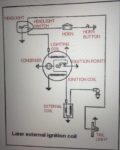
Motobecane 6V 1968 Euro model

 Euro version: They were much simpler. No brake light and less watts.


Moto Guzzi Robin (Chiù)
sheet frame, Benelli engine
Dansi 101441 magneto
internal ignition ground

Moto Guzzi Wiring: There are two kinds of Moto Guzzi Robin. They have the same name but different frames and wiring. Moto Guzzi made a stamped sheet-metal frame model, called Chiù in Europe, and Robin in the US. They also sold a Robin with a mono-tube frame made by Seimm. Both kinds had the 1970’s Motobi (Benelli) moped engine, with a Dansi 3-wire magneto.

Moto Guzzi Robin (mono-tube) The mono-tube Moto Guzzi Robin is identical to a Benelli G2. The Dansi 3-wire magneto had an external ignition ground on the green wire. It must always be connected to ground to have spark.

Moto Guzzi Robin (sheet frame) The sheet frame Moto Guzzi Robin is the US version of Chiù. The Dansi 101441 3-wire magneto had an internal ignition ground. It would never loose spark because of loose brake light wires, but the lights are not as bright.


Motobecane Sebring Morini MO1 or MO2 Dansi 101286 magneto external ignition ground
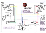
Motobecane Sebring
Morini MO1 or MO2 eng.
Dansi 101286 magneto
external ignition ground

Motron Wiring Diagram Minarelli V1 engine CEV 3-wire magneto external ignition ground

Motron Wiring Diagram
Minarelli V1 engine
CEV 3-wire magneto
external ignition ground
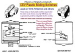
Motron Sliding Switches

Motron Sliding Switches
left,CEV 8188 lites & horn
rt, CEV 8189 engine stop

Motron Wiring: Functionally the same as the “Minarelli Wiring”. 1978-79 had the CEV clamp-on plastic slide switches. 1980-81 had the CEV “diamond” switches integrated (fitted into) the Domino controls. 
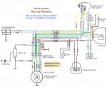


Murray Wiring (same as Puch)

Murray Wiring Diagram
Bosch 6-wire magneto
external ignition ground

Murray Wiring: Same as Puch Series B. Bosch 6-wire with external ignition ground powering the horn. Ignition, brake light, tail light, and head light all have separate source coils (armatures). Ground the blue/black wire first if there is no spark.


N=====================
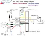
NVT Easy Rider Wiring Morini MO1 or MO2 eng Dansi 101286 magneto internal ignition ground

NVT Easy Rider ER1,ER2
Morini MO1 or MO2 eng
Dansi 101286 magneto
internal ignition ground

Negrini Wiring: The wiring diagram is not in the owners manual by MMI. See Morini Wiring. What number is on the magneto flywheel determines one of two possible wiring schemes. See Morini Wiring and Dansi Magnetos.


NVT Wiring: NVT (Norton Villiers Triumph) mopeds and motorcycles are made in England. The Easy Rider ER1 and ER2 mopeds all use the Dansi 101286 magneto, according to the owners manual wiring. On that magneto/generator, the lighting coil is split into two concentric coils, one for brake light and horn (black wire), and one for head light, tail light, and speedo light (green wire). The other coil is ignition (red wire), with an internal ground, so it is isolated from the lights. 


O=====================

Odyssey Wiring: Odyssey mopeds and engines are made in Germany by Solo. They have German style wiring with separate generator wires for each light. Euro models have a Bosch 0212 005 011 80mm clockwise magneto. USA models have a Bosch 0212 124 039 90mm clockwise magneto. More to follow…

P=====================
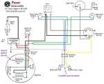
 

Pacer Wiring Diagram for Dansi magneto 101286 internal ignition ground

Pacer Wiring Diagram
for Dansi mag 101286
internal ignition ground
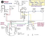
Pacer Wiring Diagram for Dansi magneto 101765 external ignition ground

Pacer Wiring Diagram
for Dansi mag 101765
external ignition ground

Pacer Wiring: Pacer is an Italian moped with either a Morini MO1, MO2, or M1 engine. Early models with frame number 15499 and below, all have the Dansi 101286 3-wire 3-coil magneto, with the ignition source coil grounded internally. Later models with frame number 15500 and above can have either 101286 or the Dansi 101765 3-wire 2-coil magneto. The only way to tell is by the number stamped on the flywheel. The brake light switches, wiring harness, and tail light are different for each magneto type. See also Morini Wiring.


Peugeot Wiring: Peugeot was one of 3 or 4 moped makers that made their own magneto. The French maker chose to be different and make their flywheel have puller threads M20x1.0, instead of the Germans M22x1.5 or Italians M19x1.0. Pre-1980 Peugeots have an external ignition ground running the brake light. Remove the tail light assembly or unplug the wires and it won’t run. Ground the black wire under the engine by attaching it somewhere to ground (such as the tail of the decomp cable wire), to get spark, when there is no spark. 1980 and later Peugeots do not have that problem, because they have an internal ignition ground. Their ignition does not rely on any of the lights.

Peugeot 103 (USA) 1976-79

Peugeot 103 1976-79
103 LS, 103 LVS, 103 SP
3-wire + spark magneto
internal transformer with
external ignition ground
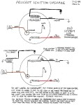
Peugeot Ignition Upgrade: Internal to ext. transformer

Peug Ign Upgrade:
int to ext trans. coil

Peugeot Ignition Upgrade: Way back in the mid 1980’s, Peugeot 103 mopeds, 1976-1979 began to burn up condensers and points rapidly. Some of the  coils would send voltage spikes. In the late 1980’s the supply of coils and stators had pretty much been used up. By 1990, even brand new Peugeot coils would not work good for long. They were going bad just sitting on the shelf. Out of desperation Shaun found a substitute inner source coil, from a Puch. It fits the Peugeot coil bolts, if they are bent in a little. A Puch outer coil (transformer) was added onto the right frame near the carburetor. ’78-79 and some ’77 103’s already have the external coil mount. 1977-earlier has to be welded on.  There is a whole chapter about that here.


These 1980 and later Peugeot models already have the upgraded ignition, with external transformer coil.
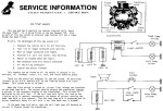
Peugeot 102,103 1980-on new “star” magneto

Peugeot 102,103 1980-on
new “star” magneto
internal ignition ground
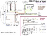
Peugeot 102,103 80-83 w/star mag, int ign gnd

Peugeot 103 1980-83
103 LS,LVS,SP,SPB, TSM
3-wire “star” magneto
internal ignition ground
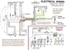
Peugeot 102 1980-83 w/star mag, int ign gnd w/tail light transformer

Peugeot 102 1980-83
w/tail light transformer
3-wire “star” magneto
internal ignition ground


 Piaggio Wiring: Vespa is one brand of the parent company Piaggio. For 1970’s Vespa mopeds, there many wiring diagrams with photos and service info, located in a separate Service section, under Vespa Electrical https://www.myronsmopeds.com/category/vespa-electrical/


Puch Wiring: All 1978-1986 Puch mopeds, USA models, have a 6-wire Bosch magneto, with points, and with an external ignition ground that powers the horn. Unplugging one of the horn wires, then pressing the horn button stops the engine. In addition to that, loosen the horn/light switch clamp from the handlebar, and a brand new Puch will not run, because of disconnected horn wires. Really! Puch is the only maker that chose to meet the USA standards that way. Almost everyone else chose to power the brake light with the ignition ground. Maybe the others figured if you’re already using the brakes and your engine dies, it’s not as bad. 
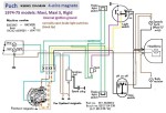
Puch 1974-75 (4-wire) Maxi, Maxi-S, Rigid (GN) Maxi 8353263-8421028 Rigid 6539521-6547172 4-wire Bosch magneto 1-speed: 0212 124 038

Puch 1974-75 (4-wire)
Maxi, Maxi-S, Rigid (GN)
Maxi 8353263-8421028
Rigid 6539521-6547172
4-wire Bosch magneto
1-speed 0212 124 038
internal ignition ground
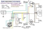
Puch 1976-77 (5-wire) Maxi-N, Maxi-S, Nostalgic Maxi 8421029-8709891 Rigid 6547173-6830115 5-wire Bosch magneto 1-speed: 0212 124 042

Puch 1976-77 (5-wire)
Maxi-N, Maxi-S, Nostalgic
Maxi 8421029-8709891
Rigid 6547173-6830115
5-wire Bosch magneto
1-speed 0212 124 042
internal ignition ground
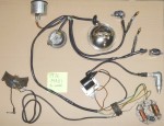
Puch 1976-77 (5-wire) actual wiring laid out

Puch 1976-77 (5-wire)
Maxi-N, Maxi-S, Nostalgic
actual wiring laid out
ULO 2-bulb tail light
Merit chrome switches
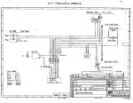
The original 6-wire plans, for US models, where the ignition powers the horn.

Puch Schaltplan Jun-77
The original 6-wire plans,
for US models, where the
ignition powers the horn.
external ignition ground


Puch 1977-78 (6-wire) Maxi, Maxi Luxe, Rigid Maxi 8709892-??????? Rigid 6830116-??????? 6-wire Bosch magneto 1-speed 0212 124 043

Puch 1977-78 (6-wire)
Maxi, Maxi Luxe, Rigid
Maxi 8709892-???????
Rigid 6830116-???????
6-wire Bosch magneto
1-speed 0212 124 043
external ignition ground
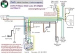
Puch Wiring Diagram 1978-79 6-wire magneto chrome switches

Puch 1978-79 (6-wire)
Maxi, Maxi II, Luxe, Rigid
6-wire Bosch magneto
1-speed 0212 124 043
2-speed 0212 124 044
external ignition ground
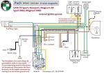
Puch 1978-79 (6-wire) Sport, Newport, Magnum Sport MkII, Magnum MkII 1-speed 0212 124 043 2-speed 0212 124 044

Puch 1978-79 (6-wire)
Sport, Newport, Magnum
Sport MkII, Magnum MkII
1-speed 0212 124 043
2-speed 0212 124 044
external ignition ground
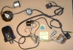
Puch 1978-79 (6-wire) Sport, Newport, Magnum Sport MkII, Magnum MkII w/square black switches CEV 2-bulb tail light

Puch 1978-79 (6-wire)
Sport, Newport, Magnum
Sport MkII, Magnum MkII
w/square black switches
CEV 2-bulb tail light
external ignition ground
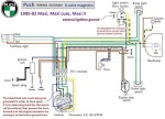


Puch 1980-82 (6-wire) Maxi, Maxi II, Maxi Luxe 1-speed 0215 254 658 2-speed 0215 254 674

Puch 1980-82 (6-wire)
Maxi, Maxi II, Maxi Luxe
1-speed 0215 254 658
2-speed 0215 254 674
external ignition ground
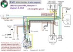
Puch 1980-82 (6-wire) Sport MkII, Newport II, Magnum II, MkII 2-speed 0215 254 674

Puch 1980-82 (6-wire)
Sport MkII, Newport II,
Magnum II, MkII
2-speed 0215 254 674
external ignition ground
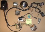
Puch 1980-82 (6-wire) Sport MkII, Newport II Magnum II, MkII w/square black switches CEV 2-bulb tail light

Puch 1980-82 (6-wire)
Sport MkII, Newport II
Magnum II, MkII
w/square black switches
external ignition ground
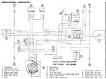
Puch 1980-82 (6-wire) Magnum MkII, Limited Ed with ignition key switch 2-speed 0212 124 044

Puch 1980-82 (6-wire)
Magnum MkII, Limited Ed
with ignition key switch
2-speed 0215 254 674
external ignition ground
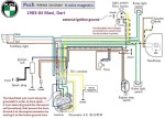


Puch 1983-86 (6-wire) Maxi, Dart with 6VAC voltage regulator 1-speed 0215 254 658

Puch 1983-84 (6-wire)
Maxi, Dart with
6VAC voltage regulator
1-speed 0215 254 658
external ignition ground

Puch Wiring Diagram 1983-86

Puch 1983-84 (6-wire)
Maxi, Dart with
6VAC voltage regulator
original b & w diagram
external ignition ground
Puch 1983-84 (6-wire) Dart, Maxi Merit chrome switches

Puch 1983-84 (6-wire)
Dart (shown), Maxi
Merit chrome switches
external ignition ground
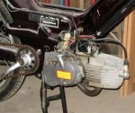
Puch 1984-86 (6-wire) Maxi Sport LS, LS II Cobra, Cobra II w/square black switches

Puch 1984-86 (6-wire)
Maxi Sport LS, MS LS II
Cobra, Cobra II, ’85 Maxi
w/square black switches
external ignition ground


Puch Korado Wiring 1995 made by Manet

Puch Korado Wiring
1995 made by Manet
CDI 2-wire magneto
(internal ignition ground)

Puch Re-makes: After the last Austrian made Puch in 1986, three companies have reproduced the 1980’s Puch mopeds. Piaggio (Italy, early 90’s), Hero (India, late 90’s), and Manet (Hungary, late 90’s). While the most of engine is the same, the electrical equipment and wiring is different, more modern. All 1990’s and later mopeds have CDI ignitions with an internal ignition ground. Thanks to the advent of electronic solid state voltage regulation in the mid 1980’s, allowing stronger magneto/generators (50 or 80 watts instead of 30) without bulb burnout, modern mopeds don’t need to borrow “juice” from the ignition, so their ignition is separate from the lights or horn, and thus way more reliable.


Q=====================

R=====================
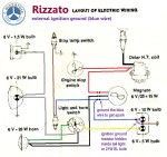
Rizzato Califfo Wiring CEV 3-wire magneto external ignition ground

Rizzato Califfo Wiring
CEV 3-wire magneto
external ignition ground

Rizzato Wiring: Italian made Rizzato has it’s own engine, with either a CEV 6952 or a Dansi 3-wire magneto. Rizzato Califfo uses the same wiring and wire colors as Italian-made mopeds with Minarelli engines. Red is ignition, black is lights, and blue (for CEV) or green (for Dansi) is an external ignition ground, powering the brake light. Unpluging the brake light wires on a Rizzato will make it stop running. When it has no spark, always ground the blue wire first. Outside wiring disconnected is often the cause.


S=====================

Sachs/Hercules Wiring: Sachs mopeds, made by Nürnberger Hercules Werke GMBH, should not be confused with mopeds that have Sachs engines, like General, Grycner, Clinton, Colombia, AMS, Foxi, Sparta, Flying Hercules smallDutchman, Eagle, and many others. Most of the “true” Sachs mopeds can be identified by the Hercules “H” logo stamped into the headlight mounts. Sachs early models, roughly 1976-1978, had an internal ignition ground. Those never lost spark because of bad brake light wires. Sachs later models, roughly 1978-1981, had an external ground. Those had a secret ignition ground resistor hidden inside the CEV 2-bulb tail light. If that went bad, the ignition would not have spark when either brake was applied (or all the time, if the brake light switch wires were loose). In that case attach the ignition ground wire, that comes out of the engine, to ground. It’s blue/black for Bosch magnetos, and black for Motoplat magnetos. That will restore the spark, but disable the brake light, for emergency use or troubleshooting.

Sachs/Hercules Wiring for Hercules-made mopeds with Sachs 505 engines (pedals inside engine):
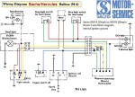
Sachs Balboa M-4 (USA) Bosch 5-wire magneto internal ignition ground

Sachs Balboa M-4 (USA)
Sachs 505/1A or 1B eng
Bosch 90mm 5-wire mag
internal ignition ground
ULO 2-bulb tail light
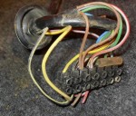
Sachs 1980 Suburban wires inside head light

Sachs 1980 Suburban
wires inside head light.
Behold, the “mystery”
diode that powers the
horn from the ignition.
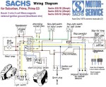
Sachs Suburban,Prima,G3 Bosch 3-wire magneto external ignition ground

Sachs Suburban,Prima,G3
Sachs 505/1D, 1A, 1B
Bosch 3-wire 90mm mag
external ignition ground
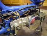
Sachs Suburban 1978-on shows magneto wires plug Sachs 505/1D engine Bosch 90mm 3-wire mag external ignition ground

Sachs Suburban 1978-on
shows magneto wires plug
505/1D with Bosch 3-wire
external ignition ground
CEV 2-bulb tail lite w/res


Sachs/Hercules Wiring for Hercules-made mopeds with Sachs 504 engines (pedals outside engine):
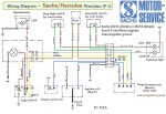
Sachs/Hercules P1 (USA) Westlake, ? Bosch 4-wire magneto

Sachs Westlake P-1 (USA)
made by Nürnberger
Hercules Werke GMBH
Sachs 504/1A or 1B eng
Bosch 4-wire 80mm mag
internal ignition ground
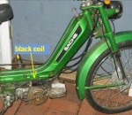
Sachs 1978 Westlake P-1 Sachs 504/1A engine Bosch 4-wire magneto internal ignition ground identified by black coil

Sachs 1978 Westlake P-1
504/1A w/Bosch 4-wire 
internal ignition ground
identified by black coil
ULO 2-bulb tail lite
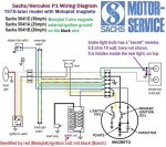
Sachs Westlake,Sundancer 1978-later Sachs 504/1D,1A,1B Motoplat 3-wire magneto external ignition ground

Sachs/Hercules 1978-on
Westlake,Sundancer (P-1)
Sachs 504/1D,1A,1B
Motoplat 3-wire magneto
external ignition ground
Sachs 1978 Westlake P-1 504/1D Motoplat 3-wire external ignition ground identified by red ign coil

Sachs 1978 Westlake P-1
504/1D Motoplat 3-wire
external ignition ground
identified by red ign coil
CEV 2-bulb tail lite w/res
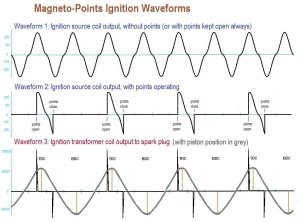


Ignition Waveform

Ignition Waveforms: Interrupted AC 
Curve 2 shows how the points interrupt the source,
and cause the unused negative triangular sections.
On a Hercules, they get less when the horn is used.
On all other bikes those minus voltages are unused.

“Mystery” Diode: All Hercules-made mopeds borrow electric power from the ignition wire (not the ignition ground) to power the horn. Normally this would kill the spark. But the wise Germans found some unused power. It’s a little hard to understand, without lots of pictures and hand waving. The flywheel has four bar magnets aligned N to N and S to S, so there are two Norths and two Souths per revolution. The current generated reverses direction every 90 degrees. The points open (the spark moment) near one of the magnetic maximums, say North. About 45 degrees later, the field is zero, and heading South. The points stay open for about 20 or 40 more degrees. That’s when there’s a short period of available reverse current/power. (When the points finally close, a secondary weaker spark occurs, with reverse polarity, but has no effect on the already burned gas.) The diode allows that reverse current to flow to the horn instead of to the spark coil, so no secondary reverse spark is produced at the spark plug when the horn is on. The diode one-way-gate stops the forward current from flowing out to the horn, so the main spark is not affected. The main spark only needs the forward current and not the reverse. 

Always disconnect the power diode, aka “Mystery Diode”, and the engine stop switch, when troubleshooting for no spark, on a Hercules-made moped. It’s either inside the head light, or down near the engine. It is for making the horn not dim the headlight.
Sachs 1978 P-1 Sachs 504/1D engine Motoplat 3-wire magneto ignition coil on top lites coil on bottom

Sachs ’78 P-1 with 504/1D
Motoplat 3-wire magneto
top: ignition – blue, black
bottom: lites coil – yellow


Motoplat (made in Spain) 80mm magneto/flywheels used on some Hercules, Sparta, and KTM mopeds with Sachs 504 engines are gold colored, and have the number 9600089. The wires are yellow = lights, blue = ignition, black = ignition ground. Their points have a built-in red wire. Condenser is CEV-compatible.

Motoplat 80mm flywheels used on 1976-86 Derbi mopeds have the number 9600099. Those wires are red = lights, green = ignition, blue = ignition ground. Their points are different, and also have no built-in wire. Condenser is CEV-compatible.


Kromag/Sears Wiring Sears Free Spirit, uses Puch 1977-78 (6-wire) 6-wire Bosch magneto 1-speed 0212 124 043

Sears Free Spirit Wiring
Puch 1977-78 (6-wire)
external ignition ground

Sears Free Spirit Wiring: The Free Spirit moped, made by Kromag, has the same wiring and electrical equipment as 1977-78 Puch Maxi (6-wire). In fact, the whole bike is Puch, but it doesn’t say “Puch” anywhere on it. All of the brand markings have been removed, to make it seem like Sears made it. Like all the Bosch 6-wire magneto Puch wirings, the blue/black wire that powers the horn is an external ignition ground for the source coil. Unplug the horn wires and loosen the light/horn switch clamp from the handlebar, and a Free Spirit will loose spark and not run. Also, like 78-later Puch, the horn button does the opposite of all other horn buttons in the world. It is normally closed, and when you push, it is momentarily open. If you replace it with any other horn button, the horn would be on all the time, and go off when you push the button. To eliminate the chance of loosing spark due to bad horn wires, simply gound the blue/black magneto wire at the terminal strip above the engine, by moving it over to the brown wire that goes to ground.
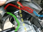
Solex Parts Figure 20 1973-74 S 3800 USA Lights Wiring

Solex 3800 Wiring
1973-74 S 3800 USA
1-wire + spark magneto
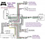
Solex 4600

Solex 4600 (USA) Wiring
3-wire + spark magneto
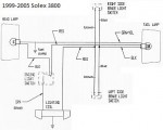
Solex 3800 Impex

Solex 3800 Impex
Lights Wiring only
points or CDI magneto

Solex Wiring: The 1970’s and earlier Solex 3800 had only one wire outside of the engine, going to the tail light. Instead of wires, the head light and switch had direct contacts. The ignition spark coil was internal, with the spark plug wire coming out of the magneto. 
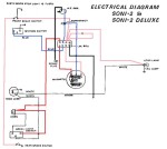


Soni 2 Wiring Diagram India made Vespa Ciao

Soni 2 Wiring Diagram
India made Vespa Ciao
3-wire points magneto
external ignition ground
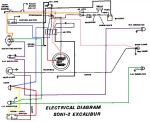
Soni 2 Excalibur Wiring Vespa Ciao India remake

Soni 2 Excalibur Wiring
turn signal model
India made Vespa Ciao
3-wire points magneto
external ignition ground

Soni Wiring: This 1980’s India remake of a 1970’s Italian made Vespa/Piaggio moped, has functionally the same wiring, pretty much, as Vespa did. Unlike the Kinetic, a 1990’s India made Vespa remake, that has a CDI ignition, the Soni has points, and an external ignition ground magneto that powers the brake light, like Vespa/Piaggio. When we say “ground the pink wire to get spark if the brake light filament burns out”, in India they say “earth when stop light is fused”. It looks like it has an emergency wire that would allow it to run if it lost spark from a blown brake light bulb or loose wire.
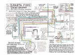


Sparta (US models) Flying Dutchman, Foxi

Sparta Foxi, early F.D.
with many notes added
ULO 2-bulb early taillight
Bosch 4-wire magneto
internal ignition ground

Sparta (with Bosch magneto) 1976-78 models Bosch 4-wire magneto internal ignition ground

Sparta (with Bosch)
’76-78 Foxi, F.D, Sparta
ULO 2-bulb early taillight
Bosch 4-wire magneto
internal ignition ground

Sparta with Motoplat wiring diagram showing brake light resistor-diode circuit

Sparta (with Motoplat)
’78-81 Dutchman, Sparta
ULO 2-bulb taillight w/res
Motoplat 3-wire 9800089
external ignition ground

Sparta Wiring: Sparta had two 80mm magneto versions for the Sachs 504 engine, Bosch 4-wire and Motoplat 3-wire. The wires on the bike are the same, except Motoplat version has an external ignition ground, a tail light secret resistor, brake switch type NC not NO, and the brake switches wired in series, not parallel. The Motoplat version needs the brake light wires and correct bulb to have spark.

One way to tell which (brake light) wiring and magneto version a Sparta has, from a distance, is by the color of the ignition coil and plug wire. Motoplat is red, while Bosch is black. It’s the same situation as Hercules/Sachs wiring. Spartas with red coils have normally closed (white or brass tip) brake light switches in series, and a secret brake light resistor-diode circuit board inside the tail light. Spartas with black coils have normally open (black tip) brake light switches in parallel, and no brake light resistor inside the tail light.


Suzuki Wiring: The early 1980’s Suzuki FZ50 (3.00 x 12″ tires) and FA50 (2.25 x 14″ tires) have pretty much the same engine, controls, wiring, and electrical equipment.
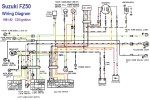
Suzuki FZ50 1981-82 FA50 maybe same 5-wire CDI magneto

Suzuki FZ50 1981-82
5-wire CDI magneto

Suzuki FA50 1981-91
5-wire CDI magneto
Suzuki FA50 wires needed to have spark


T=====================

Testi Wiring: Testi makes Gitane, Red Foxi, and other makes with Minarelli V1 engines. See Minarelli Wiring.

Tomos Wiring: Here is a complete, detailed, and accurate set of wiring diagrams. These took 200 hours, over a 3-month period, to gather, interpret, colorize, and edit for clarity. Many of the originals were terribly inadequate, although functionally correct. 
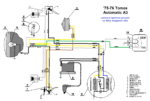
Tomos Automatic 75-76
3-wire mag, ext. ign gnd
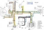
Tomos A3 Bullet 1976-86 3-wire mag, ext. ign. gnd.

Tomos A3 Bullet 77-86
3-wire mag, ext. ign gnd

Tomos A3 Bullet 1986-91 2-wire mag w/regulator internal ignition ground for improved reliability
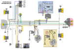
Tomos A3 Bullet 86-91
2-wire mag w/regulator
internal ignition ground
for improved reliability


Tomos A3 Silver Bullet
early Golden Bullet 85-86
3-wire mag, ext. ign. gnd.

Tomos A3 Golden Bullet & Golden Bullet TTLX 1986-91 int. ign. gnd.
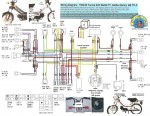
Tomos A3 Golden Bullet
& Golden Bullet TTLX
1986-91 int. ign. gnd.

Tomos A35 Bullet 92-93

Tomos A35 Bullet 92-93
Iskra 2-wire magneto
internal ignition ground
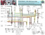


Tomos A35 Colibri 92-96

Tomos A35 Colibri 92-96
Iskra 2-wire magneto
internal ignition ground
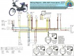
Tomos Sprint 1993-97

Tomos Sprint 1993-97
four different magnetos
internal ignition ground
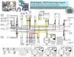
Tomos Targa 1994-95 Tomos Targa LX 94-95

Tomos Targa 1994-95
Tomos Targa LX 94-95
four different magnetos
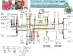


Tomos Targa 1996-97
Tomos Targa LX 96-97
Iskra 2-wire CDI magneto
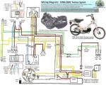
Tomos Sprint 1998-01

Tomos Sprint 1998-01
Iskra 2-wire CDI magneto
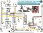
Tomos Targa 1998-01 Tomos Targa LX 98-01
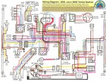
Tomos Targa 1998-01
Tomos Targa LX 98-01

Tomos Revival 2001-02

Tomos Revival 2001-02
Iskra 3-wire CDI magneto
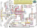


Tomos Revival 2002-07

Tomos Revival 2002-07
Iskra 3-wire CDI mag A35
Iskra 5-wire CDI mag A55
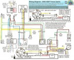
Tomos Sprint 2002-07

Tomos Sprint 2002-07
Iskra 2-wire CDI mag A35
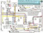
Tomos Tomos 2002-05 Tomos ST 2005-2007 Tomos LX 2002-2007
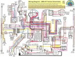
Tomos Tomos 2002-05
Tomos ST 2005-2007
Tomos LX 2002-2007

Tomos Streetmate 05-07

Tomos Streetmate 05-07
Iskra 5-wire CDI mag A55
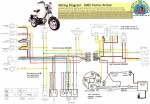


Tomos Arrow 2005

Tomos Arrow 2005
Iskra 4-wire CDI mag A55
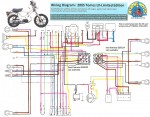
Tomos LX Limited Edition 2005

Tomos LX Limited Ed. 05
Iskra 3-wire CDI mag A35
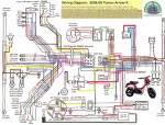
Tomos Arrow-R 2006-08

Tomos Arrow-R 2006-08
Iskra 5-wire CDI mag A55
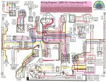
Tomos Revival 2008-12+

Tomos Revival 2008-12+
Kinetic 5-wire CDI mag
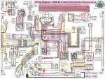


Tomos Streetmate 08-12 Tomos Str.mate-R 08-13

Tomos Streetmate 08-12
Tomos Str.mate-R 08-13
Kinetic 5-wire CDI mag
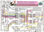
Tomos Sprint 2008-13 Tomos ST 2008-2013 Tomos LX 2008-2012

Tomos Sprint 2008-13
Tomos ST,LX 2008-2013
Kinetic 5-wire CDI mag


Trac Wiring: Trac mopeds were made in Korea by Dailim (DMC). Early Tracs were a mix of European and Asian components and designs.

Trac Clipper, Eagle, Hawk 83-86 Dailim M56 Engine Bosch 3-wire magneto external ignition ground

Trac 1982-84  Clipper,Eagle,Hawk
Daelim M56 engine
Bosch 3-wire magneto
external ignition ground

Trac 1985-86 Clipper,Eagle,Hawk Dailim M56 Engine Bosch 3-wire magneto external ignition ground

Trac 1985-86 Clipper,Eagle,Hawk
Daelim M56 Engine
Bosch 3-wire magneto
external ignition ground


Later Tracs were all Asian, with wire colors same as Honda.

Daelim ignitionThe DMC DP50 (one-speed with pedals) used on Olympic, Clipper, Hawk and DM50 (two-speed kickstart) used on Liberty, Image, Escot, engines both had a 5-wire CDI magneto. White = battery charging, yellow = head light, blue/white = ignition pulse, black/red = ignition power, green = ground.

Trac Wiring 1986-89 Liberty, Image, Escot CDI 5-wire magneto internal ignition ground

Trac 1986-89 w/signals
Liberty, Image, Escot    Daelim DK50 2-speed
CDI 5-wire magneto
internal ignition ground
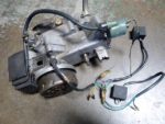
Trac Daelim DK50
wires needed for spark
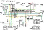
Trac DH100 Super Hawk 3-wire magneto in oil bath points up on th OH cam 6V 6Ah battery, 6V lites

Trac DH100 Super Hawk
3-wire oil bath magneto
points up on the OH cam
6V 6Ah battery, 6V lites

<<There are two CDI units that look the same. Here the key switch is bypassed by joining the two black/red male bullets. The engine stop button (black/white) is also disconnected. This apparatus has good spark, when the wheel is spun counterclockwise by hand. Note that the coil is grounded.


The DMC DH100 (4-speed 97cc 4-stroke overhead cam motorcycle) had a 3-wire magneto/generator down in the oil bath, with external points and condenser up on the overhead cam. Very much the same as a Honda 90, except the Trac had a ignition source coil in the generator, while most versions of Honda 90’s did not . A 1986 Trac DH100 would run with a dead or missing battery, but a 1971 Honda Trail 90 would not. These similar small motorcycles are examples of the difference between a battery ignition and a magneto ignition system.  


U=====================
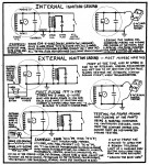
Universal Ign Wiring Ext & Int Ground very important

Universal Ign Wiring
Ext or Int Ground
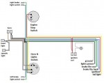
Universal Wiring Harness brake light wires can be either NO in parallel or NC in series

Universal Wiring Harness
brake light wires can be
norm open in parallel or
normally closed in series
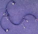
Italian wiring harness

Universal Wiring Actual
this is for sale in electrical
also in Morini Wiring


V=====================

Vespa Wiring: There many wiring diagrams with photos and service info. They are located in a separate Service section, under Vespa Electrical https://www.myronsmopeds.com/category/vespa-electrical/


W=====================
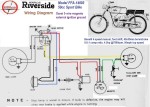
Wards Riverside Wiring Dansi 3-wire magneto external ignition ground

Wards Riverside Wiring
Dansi 3-wire magneto
external ignition ground

Wards Riverside Wiring: Mongomery Wards in the late 1960’s sold a full line of motorcycles and mopeds made in Italy by Benelli (and also early 1960’s mopeds made in France by Motobecane). This is the 50cc sport bike model FFA-14003, a 4-speed foot shift manual clutch motorcycle. Even back then, they used the ignition source coil ground to operate the brake light. Ground the green wire first to get spark. 


X=====================


Y=====================
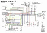
Yamaha QT50 Wiring Diagram

Yamaha QT50 Wiring

Yamaha Wiring: Yamaha made the QT50 Yamahopper moped (actually “no-ped” or “mokick”) from 1979 to about 1983. There are 2 or 3 wiring and electrical equipment versions. more later… 


Z=====================
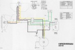
Zundapp ZD40 Wiring

Zundapp ZD40 Wiring
Euro model w/brake light
internal ignition ground
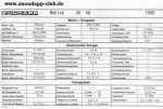
Zundapp zd40 Specs

Zundapp ZD40 1980 
3-speed mokick specs
Bosch 0212 122 026 mag
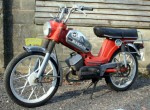
1977 Zundapp ZD40 pedal start moped 3-speed grip shift aluminum frame

Zundapp ZD40 1977 
pedals,3-spd, alum frame

Zundapp mofas, mopeds, and mokicks were never sold in the US. The “BMW of mopeds” is included in the wiring party because Zundapps are easy to admire! Too bad “ZD40” means 40kph  (26mph). 


Welcome to Myrons Wiring Diagrams Gallery. Mopeds have strange electrical wiring. Many have “secret” wires that must be grounded to run. Many have switches that normally would turn off something, but instead they turn on something (brake light or horn). Most of the wiring diagrams explain this, when it applies. This “secret wire that must be grounded to run” system is only on most 1970’s and 1980’s US models. The reason for this craziness is that European mopeds do not need brake lights, but US ones do. So many kinds power the brake light from the back side of the ignition source coil. One kind, Puch 77-later, 6-wire, powers the horn from the back side of the ignition source coil. So on a 77-on Puch, if you unplug the horn and push the horn button, the engine dies. Besides loosing spark, older mopeds also often burn out light bulbs. That is because a magneto generator alone, without a battery or regulator, ranges from dim lights at idle, to bright at full speed. So your bulbs are either too dim, or else they burn out a lot. Modern (1990-later) mopeds don’t have the old moped wiring problems. They run a more powerful magneto, 70-80 watts instead of 30-40. All the lights run off one wire, with a 12VAC voltage regulator. To keep the voltage below about 13V, the regulator passes any excess current into the frame where it’s mounted. So when most of the lights are off, the frame is being warmed a lttle. This “regulation by wasting” system is common on motorcycles but not automobiles. Also nothing that the lights do ever matters to the ignition. Magneto ignitions after about 1993 are CDI (Capacitor Discharge Ignition) instead of points. They’re also maintainence free and have easier starting.  


New Tomos Electrical

August 13, 2008

Welcome. Scroll down to the topic you want:

1) Basics of Tomos Moped Electrical Systems   Everything is Circuits, Shorts and Opens, Volts and Amps, Batteries and Generators, Magnetos, Magneto versus Battery, Testing without a Tester, Example 1: Prince of Darkness, Example 2: The Flasher, Make predictions, AC lights and DC lights, Example 3: The Double Crosser, Example 4: The Flickerer, Example 5: The No Charger

2) Tomos Voltage Regulators 1988 to 2013  Here are the 12 volt AC regulators, three types. One is also a rectifier.

3) Tomos CDI Ignitions 1994 to 2013    Ignition, How to Test a Coil, How to Check for Spark, Ground the Coil Wire to Stop the Spark, Tomos  A35 and A55 CDI Ignitions, Ignition Timing, Ignition Symptoms

4) Tomos Wiring Diagrams 1992 to 2013  Here are over a dozen wiring diagrams, colorized and enhanced with notes, part numbers, and additional useful information.

Basics of Tomos Moped Electrical Systems

by Shaun Strahm, Myrons Mopeds, December 2010, updated Nov 2012

The following is a “crash course” on how to find and fix electrical problems on late model TOMOS mopeds.

Everything is circuits

Every electrical system is composed of current loops or circuits. The electricity flows out, goes through the device being powered, and then flows back. That is why all electrical cords have at least two wires. One wire is out and one is back. Coaxial cables look like one wire, but they’re actually one wire surrounding another. If you follow that pair of wires in an appliance cord all the way to the transformer on the power pole, you’ll see they’re joined in the windings of the transformer, forming a closed loop.  In some electrical systems such as automobiles and mopeds, the metal frame is a “ground”. In this context a “ground” is a path for the electricity to flow through that is shared by many loops. If the cars in a big city were electricity, then each current loop would be one car, going to work in the morning and then coming back in the evening, making a loop. Then the freeway would be the ground, where the separate current loops all share the same roadway.  When several devices are connected with each having its own current loop, they are said to be connected in “parallel”. Unplug one device and the others are unaffected. Everything in your house is wired in parallel, and has its own current loop. Similarly, on a moped, the head light, tail light, brake light, and horn are wired in parallel, and have their own separate loops or circuits. The tangled nest of cords behind your computer desk, as well as the wires in your moped, can, in principle, be laid out in nice straight parallel lines in order to visualize the “scheme”. This is called a “schematic” diagram. Being able to visualize or draw the schematic is required to understand any circuit.


Figure 1: Schematic diagrams of a moped and a house are the same. Every device is in a “parallel” loop or circuit.

     When two devices are connected one after another, they are said to be “in series”. The only things on a moped or in your house that are in series with other things are the switches. From figure 2 below, you can see from the house wiring diagram that the TV switch turns on the TV and not the computer. You can see that the breaker turns off everything. From the moped wiring diagram you can see that the light switch turns off the lights but not the horn. This is basic.

Figure 2: The devices in a moped and a house are in parallel, while their on/off switches are in series.

You can usually tell how a moped or a house is wired from observing the behavior of all the switches and devices. Any switches must be in series with the devices they turn on and off. Each device and its (optional) switch must be in parallel so that they can be turned on and off independently of one another. This is predicting the wiring diagram from the observed behavior. Conversely, you can also predict the behavior from observing the wiring diagram.

Shorts and opens

Not every electrical problem is a “short”. The term “short” is unknowingly misused by the general public to mean two opposite things at once, a “short circuit” and an “open circuit”. It can mean a true short, where a wire (or anything that carries electricity) touches another, forming a shorter loop that redirects the electricity through the short loop and not through the original loop. Or the term “short” is misused to mean an open, where a wire (or anything that carries electricity) does not touch another, interrupting the loop and causing the electricity to not flow through the loop. Both a short and an open can cause electricity to not flow through a device, but for completely opposite reasons.

Figure 3: A “short” is a shortcut that steals most of the current from the device. An “open” interrupts the current.

Volts and amps

Electricity flowing through a wire is analogous to water flowing through a pipe. It is measured in two ways. The “voltage” (in volts), is like the water pressure (in pounds per square inch). The “amperage” (in amperes or “amps”) is like the water flow (in gallons per minute). When you’re taking a shower and someone turns on the garden hose, your water pressure drops. Less water pressure results in less water flow and your shower gets weaker. Likewise, when starting your car, all your lights get dim. This is because your 12 volt battery momentarily drops down to 6 or 8 volts when the starter motor is using up most of the available current.

Batteries and generators

There are two main sources of electricity. Batteries (and fuel cells) produce steady current, called “DC”, or direct current.  Generators (and alternators, magnetos, and dynamos), make “AC”, or alternating current. The current made by a generator alternates direction back and forth, in sync with the rotation. The rotation is what causes the electric current to be AC. All power plant generators in the USA are set to rotate at a speed that always makes 60 cycles per second AC, or 3600 cycles per minute. On a moped, the generator rotates with the engine, which varies in speed from about 1000 cycles (revolutions) per minute “rpm” at idle to above 8000 cycles per minute going fast downhill. So the “frequency” (how fast it alternates) of the AC is variable in a moped, but not in a house. Many devices such as lights, behave the same no matter what the AC frequency is. In fact an incandescent light bulb works exactly the same on AC or DC current. In figure 4 below, graphs of voltage versus time show the main types of electricity. 60 wave crests happen in about one second, so the time scale is too short for the human eye to see. Only an oscilloscope can show the “wave form”.

Figure 4: AC is from generators. DC is from batteries. In between is rectified AC or “rippled” DC.

Magnetos

Mopeds and small motorcycles have magnetos. A “magneto” is a generator plus a no-battery ignition. A magneto ignition will operate with a dead battery. Automobiles and large motorcycles have battery ignitions. They require a battery, both to operate and to start up. Dirt bikes and power equipment without lights have magnetos with a single wire output. That is the ignition wire that goes from the source coil (and points and condenser) inside the engine to the transformer coil outside the engine. All street bikes with lights have two or more wires coming out of their magnetos. One is for ignition, and the other(s) is for lights. We now focus on the lighting wires, which are normally separate from the ignition. If you turn over a moped engine, that is, cause it to rotate, then some electricity will be generated and the lights should come on while it’s being rotated. Just because the lights work does not mean the ignition works. They are like two separate generators tuning on the same shaft. As the engine rotates faster, the lights get brighter, indicating more voltage is being produced.  The magneto/generator will reach a speed where the voltage will level off. Above that speed the lights won’t get any brighter. So a magneto is self-limiting with regard to engine speed (and thus vehicle speed). The bad thing about a magneto is when you are stopped idling your lights are dim. With a battery, your lights are always almost the same brightness all the time. The good thing about a magneto is you don’t have a heavy expensive battery that goes bad if you leave it sit for over a few months.

Magneto versus battery

The most important difference between a battery and a magneto is a battery will deliver an almost unlimited amount of amps, if it is allowed to, while a magneto will limit the maximum amps by dropping in voltage. Because of this, a battery system needs fuses to protect its wires from melting from too many amps. A magneto does not ever have fuses, nor does it need them. This difference makes moped electrical troubleshooting different from automobile troubleshooting. A magneto almost never burns out or causes wires to melt. You can short a magneto’s lighting wire directly to ground, and it will only get warm. Short a battery’s positive terminal to the negative and the wire will suddenly glow red and splatter molten copper and sparks. That’s quite a difference. A battery is always “live” even when the engine is not running. A magneto, however, is only “live” when the engine is running. So when troubleshooting a magneto system, instead of starting and stopping the engine to perform voltage tests, it is more convenient to leave the engine off and perform continuity (ohms) tests on “non-live” wires. When the leads on an ohm meter touch each other, the resistance (ohms) is essentially zero. When the pair of test leads does not touch each other the resistance (ohms) is essentially infinite. Instead of watching the needle swing on a meter, a continuity tester that makes sound is better. With a tester that beeps when the leads touch, and with the leads connected to the wire being tested, you can then focus your eyes on the suspicious area and wiggle or move the wires around listening for the beep to change. When your suspicious wire touches the bad spot, the tester will beep. Or when your suspicious wire goes open, the beep will stop. This is the usual way of checking bulbs, besides looking visually for a broken filament. A good bulb will have continuity (very low ohms), while a bad bulb will have no continuity (very high ohms). You can often check a bulb without removing it from the socket, by connecting the test leads to the wires that lead to the bulb. If there are branch points along that wire that lead to other bulbs, then those other bulbs must be removed from their sockets in order to isolate the suspicious one.

Testing a without a tester

You don’t need a weatherman to know which way the wind blows. Likewise it is possible to perform useful tests with just swapping things around, unplugging things, or using paper clips or clip leads as temporary wires. When your toaster stops making toast, the first thing you do is go plug it into a wall socket that is known to work. Then if the toaster works there, you know the problem is in the wall socket. If it still does not work in the good wall socket, then you know something’s wrong with the toaster. Right there you just applied mathematical logic to perform troubleshooting. People who are good at math and logic puzzles also have an easier time solving electrical problems. The most important tool needed for electrical troubleshooting is the mushy grey stuff between your ears. Each test, when performed properly, establishes a new truth. The newly established truth forms the basis for a further test. Each successive test narrows down the possibilities, until finally there is only one possible explanation for the results of all the tests. There is almost always more than one way of troubleshooting. Instead of moving the suspicious toaster to a known good wall socket, an alternative way of troubleshooting it would be to take a known good lamp and plug it into the suspicious wall socket. If the known good lamp works there, then you know the wall socket is good and the toaster is bad. If the known good lamp does not work there, then you know the wall socket is bad but you still don’t know about the toaster.  That is the kind of precise mathematical thinking required to solve electrical problems (puzzles to some).

Example 1: Prince of Darkness

Here is a real life moped troubleshooting example. Let’s say your 2003 Tomos Sprint head light does not work. You first learn about how it’s wired from the wiring diagram. That tells you there is a head light on/off switch on the right handlebar, and a high beam/low beam switch on the left handlebar. Right away you look to see if the switch is on. If it is, then you see if switching from high to low beam matters.  On an already running bike, you would start the engine, flip the switches, and observe. If the head light worked on high beam but not low, that would mean the problem must be after the high/low switch, in the low beam (white) wire, low beam bulb socket prong, or most likely the low beam filament inside the bulb. If the head light did not work on either high or low, then nothing new is learned. Looking at the wiring diagram you can see that all of the lights work of one wire. So you would test to see if the tail light, brake light, speedometer light, and horn work. Again you would start the engine, press buttons, and observe. If none of the devices work, regardless of what position the switches are in, then it’s possible that all of the devices (head light bulb, speedometer light bulb, tail light bulb, brake light bulb, and horn) could be bad all at once. However, it’s far more likely to be a single fault in the yellow wire that supplies all the devices. There’s two ways the yellow wire can be bad. It can be touching ground anywhere along its length, from the speedometer bulb to the magneto, causing a short circuit, or it can be an open circuit somewhere before the first branching point, possibly in the magneto. Understanding that is the hardest part. The next test would be to unplug the yellow wire from the engine, start the engine, touch the yellow wire from the engine directly to ground and see if it sparks. If the generator is working, it will spark. Let’s say it does spark. Then you would look to see if it sparked when you plugged it back in, maybe using a paper clip to see sparks that might be hidden by the connector cover. If it does spark when it’s plugged in, yet none of the lights come on, it can only mean that the yellow supply wire is touching ground somewhere, allowing the current to return without going through the lights. Next step is to start eliminating the various possibilities. The AC voltage regulator is a good place to start. You would unplug it and then start the engine and see if the lights work. On a 1992-later Tomos moped you need a voltage regulator only when the engine is revved up to keep the bulbs from burning out from too much voltage (like 18 VAC max without regulator, 13 VAC max with). The lights will work fine without a regulator, but the engine must not be revved up too much. Let’s say that the test is performed, and the lights still don’t work, even with the regulator disconnected. Next possibility might be to look at the yellow wires going to each brake light switch, since they are easy to get to. Pull the rubber hoods off and let the wires hang loose, a yellow and a green on each side. Now if the brake light green wire was shorted to ground, and at the same time the yellow and green on either side were unplugged and touching each other , then the brake light would be always on, always stealing the juice from the other lights. You would start the engine with the brake light switch wires loose. Bingo! Suddenly the head light, tail light, speedometer light, and horn all work. So you would put the regulator back and then go look for the green wire touching ground somewhere. You know it must be true. You would look first under the back fender, where the tire sometimes rubs against the tail light and brake light wires. Eureka! The green wire is all shredded and touching the brown ground wire. You went from one end of the bike to the other, without any test equipment, just plugging and unplugging wires in a logical progression.

Example 2: The Flasher

In this example, a 2008 Tomos LX, turning on the right turn signal makes all the lights flash. You go to the wiring diagram and notice that all the devices run off the yellow AC power wire. You reason that if the purple wire, which is for right side turn signals, is shorted to ground somewhere, then that would explain the bad behavior. Whenever the right side turn signals would try to go on, the short would steal the current away and make all lights go off. The turn signals are plastic and almost never get shorted internally. It can happen from someone bending the prong that touches the bulb, so that it touches the bulb socket. But more likely, the purple wire is touching ground somewhere under the back fender. After looking under the rear fender and seeing no signs of wire damage from rubbing on the tire, you would start performing tests to isolate the problem. You would unplug both right turn signals. The problem would go away if it was in one of the turn signals. But it doesn’t. You study the wiring diagram and notice there are many ways you can unplug things on a 2008-later model. You might choose to unplug the main plug. From looking at the wiring diagram you would know that the front turn signals and indicator light would be eliminated, but the rear turn signals would still try to function. You perform the test, and lo and behold, the problem goes away. This means that the purple wire is touching ground somewhere from the main plug forward. You would then maybe look at the front harness where it goes up under the gas tank. A normal 2008-later Tomos Sprint, ST, or LX has the three electrical bundles and the two control cables (throttle and rear brake) distributed evenly on the right and left sides of the steering tube part of the frame. Some 2008-09 bikes came from the factory with all of the wires and cables on one side. This makes it very difficult to get the cable tray on and very likely to pinch or puncture the wires with one of the cable tray screws. You notice that your bike is like that, with the cables and wires all on one side. You loosen the cable tray screws, letting the wire bundles dangle. You plug back in the main plug and start the engine. The problem goes away. Then you notice the snake bite puncture wound the cable tray screw made in the front wiring harness. The permanent fix is to unplug the main plug, and the right switch plug, and relocate the front harness and right switch harness to the empty left side. So the right side should have the throttle cable, rear brake cable, and the left and switch harness. The left side has the hefty front harness and the slim right switch harness. With this proper routing the cables and wires almost never get damaged.

Make predictions

The troubleshooting process involves making predictions. Look at any of the Tomos moped wiring diagrams in the collection. Imagine cutting a wire or two, here or there, or touching one or more to ground. In each case a good technician should be able to predict the misbehavior of all the lights and devices for all possible cases, just by looking at the wiring diagram or visualizing it in their head. If you study each of the eighteen Tomos moped wiring diagrams in this collection and imagine what would happen when any given wire becomes open or shorted, then when you do see the real life misbehavior, you will often know right away what the possible causes are, since that scenario has already been rehearsed. For example, ask “what if the blue (high beam) wire touches ground”. Answer “all the AC lights would go off, but only when the high beam is turned on”.

AC lights and DC lights

The deluxe Tomos “battery” models, 2001 and later, including Revival and Streetmate, have both 12 volt AC and 12V DC electrical systems. Like the regular models (Sprint, ST, LX), the “battery” models use the 12V AC generator/magneto for the head light, speedometer light, and tail light. The other lights and devices, which are the brake light, turn signals, horn, oil light, and electric starter, are powered by a 12V DC battery.

Example 3: The Double Crosser

<Under construction>

Example 4: The Flickerer

On 1991-2008 Tomos A35 and 2007-2008 A55 models, excluding Revival and off road, the CEV switches are integrated into the lever and throttle housings, and cannot be unplugged from the wiring harness. To replace these switches, each wire must be carefully un-soldered and re-soldered. A micro-tip low wattage soldering iron is needed to reach in, and to not melt the black plastic housing. Sometimes when trying to not overheat the switch plastic, the solder joint is made “cold”. This is where the solder is “balled up” rather than “blended in”, where it is stuck only by the flux and not the solder. Here, the blue hi-beam wire is a “cold” solder joint. When you wiggle the wire it causes the high beam to flicker. The remedy is to re-solder it.


Example 5: The No Charger

This 2009 Tomos stator, back side,  had this wire, green arrow, smashed flat against the aluminum wall of the stator plate. It was not touching all the time. The coils do not look overheated.

This machine was a 2009 Tomos Streetmate-R, a “battery model”. It’s battery would not stay charged. The battery voltage was staying the same, whether the engine was running fast, or not at all. It should go up, from about 12 to 13 volts, when it’s charging.

You can tell from 50 yards away, blindfolded, whether or not a Tomos Revival, Streetmate, Arrow-R charging system is working, by the sound of the horn. When the battery is not being charged, like when the engine is not running, the horn sounds completely smooth. The battery voltage is a steady straight line on an oscilloscope. When the engine is running the the smooth sound becomes more rough. The battery voltage is a straight line with little repeating bumps on an oscilloscope. When you hear the rough sound in the horn, you know that the charging system is working.

The white spot is a reflection from the shiny flat surface of the black insulation, worn from vibration and contact with the stator plate. The fix was to cut away a fingernail size part of the plate.


Tomos Voltage Regulators


Tomos Voltage Regulators

Tomos regulators. Some blade connectors are duplicates (connected together inside) or unused (not connected inside).


All of the above 12-Volt Alternating Current regulators can interchange. They all regulate the voltage on the yellow wire, by dumping any excess voltage into the brown wire, that goes to the frame. They keep the AC voltage below about 13 volts. This allows the use of a stronger generator, for brighter lights when stopped and the engine is idling. The stronger generator would otherwise be too strong when the engine was running fast, and would make a voltage over 13 volts, maybe 14 or 16. That would make the lights super bright, but they would soon burn out. The regulator prevents bulb burnout from too much voltage. The bulbs can also burn out from too much vibration. The regulator would not help that. 


Tomos CDI Ignition

August 13, 2008

Table of Contents

Ignition ……………………………………………………     1

How to test a coil…………………………………….    1

How to check for spark……………………………    1

Ground the coil wire to stop the spark…..    2

Tomos A35 and A55 CDI ignitions…….……..    2

Ignition timing…………………………………………   2

Ignition symptoms………………………………….   3

Ignition

The ignition is like the electric pulses of a heart beat. The voltage pulses are in sync with the rotating crankshaft. When the crankshaft rotates faster (or slower), the spikes are closer together (or farther apart) in time. See figure 5.

Figure 5: Ignition is neither AC nor DC, but instead a train of narrow pulses, each happening at a precise time.

What makes the gasoline ignite is the spark plug sparking, in the right way, at the right time. What makes the spark jump the gap of the spark plug is a sudden very steep rise in voltage, to over 10,000 volts in under a few thousandths of a second. What makes that high voltage spike is a transformer, usually called “the ignition coil”. A transformer is like a car jack. It steps up (or steps down) voltage while stepping down (or stepping up) current. A sudden change in current in the (thicker but fewer) primary windings induces a sudden large change in voltage in the (thinner but many more) secondary windings. Supplying the transformer with a sudden change in current is either a CDI unit (Capacitor Discharge Ignition), on 1994 and later, or a mechanical points and condenser, on 1993 and earlier models. On late model Tomos mopeds with CDI ignition, the electronics are molded into the coil (unlike most Asian types). The “control unit” or “CDI unit” is a small 1.5 inch square circuit board, hidden inside the black plastic of the coil. Early models before 1994 had plain coils, without any electronics.

How to test a coil

Any ignition coil (coil only, not coil-with-CDI like Tomos uses) will produce a spark on a spark plug, at the instant the input wire is touched to a 12 volt battery (+), with the battery (-), coil, and plug all grounded (with clip leads). If you touch it slowly to the battery post, it will produce a weak spark. If you swipe the coil wire fast and hard against the battery post, it will produce a strong spark. This demonstrates that it’s the shorter “rise time”, much faster than the blink of an eye, that makes a better spark. Only perform the above spark test on plain coils. CDI/coils might get damaged from the high current possible. Never connect a 12V battery to a coil for longer than one second. It turns out that moped coils are never bad. Only occasionally the CDI/coils go bad. “Bad” means it produces no spark at all, or it produces weak or intermittent spark. Intermittent spark is like turning a light switch off and on, often in an unpredictable way. The only way to test a CDI/Coil is to put it on a known good running bike and test ride it, listening and feeling for any stumbling or misfiring. If no test bike is available, then the only way to test the CDI/Coil is to replace it with a known good one, and hope that fixes the problem. If it’s not the CDI/Coil, and not the bike’s wiring, then it must be the magneto. The CDI magneto costs way more than the CDI/Coil, and is more difficult to change, and so it’s last.

How to check for spark

CDI solid state ignitions have shorter rise and fall times than mechanical point ignitions. That makes them start with a weaker kick, or even with your hand. CDI ignitions have a faint spark that is sometimes invisible in bright sun. Always check for spark in the shade. “Checking for spark” means removing the spark plug, connecting the plug wire to it, laying it on the engine so that it’s metal shell is touching ground (the head fins), and then turning the engine over (by pedaling backward or kick starting) while watching the gap between the electrodes of the spark plug. Spark color indicates temperature. Blue spark is hotter than pink or yellow. Faint blue spark is good. Bright white spark is bad, usually because of a semi-conductor-coated “fouled” spark plug.  The white porcelain insulator must not be coated with black or shiny carbon. If it is not dull white, tan, or brown, then use a new spark plug to check for spark. A fouled plug will spark badly or not at all, even when the ignition is working fine. You can also hear the snap sound of the spark. Loud is good.

Grounding the coil wire stops the engine 

In both CDI and points type magneto ignitions, the “heart beat” is intentionally stopped when you turn the engine stop switch off. When the “kill” switch is “on” the ignition wire is not grounded. When the kill switch (engine stop) is “off” the ignition wire is grounded. This is the opposite of a (battery ignition) car. So to hot wire a magneto ignition bike you only need to disconnect or cut the kill switch wire so that it cannot be grounded. When troubleshooting a late model Tomos that has bad or no spark, the way to eliminate all the wires in the bike is to plug the black (or red) magneto ignition wire (which has a female blade connector) into the male blade of the coil (or it’s black or red wire with male blade). This isolates the circuit to just the engine and coil. Just remember you can’t turn the engine off.

Tomos A35 and A55 CDI ignitions

There are two types of Tomos CDI magneto ignitions, the A35 type (1994-2006) and the A55 type (2001-later). They consist of two or more coils mounted on a stationary plate, surrounded by a rotating flywheel with four strong magnets molded into it. The A35 ignition has no pulser coil to tell it when to spark. It triggers when the source coil voltage reaches a pre-set level. So changing the location of the source coil (by rotating the stator plate) changes the ignition timing. Tomos provides adjustment slots in the stator plate, and timing marks (thin angled black lines) on the crankcase (minimum and maximum ignition timing), at about the 10 o’clock pposition. An ignition timing strobe light is the only way to check the ignition timing. The strobe light illuminates the fast moving flywheel mark only for an instant. So it appears, magically, to be not moving. The fire mark on the flywheel should lie between the black lines on the case. It should not jump around. The light should not flicker. Once the stator is set in the desired position and the screws are tightened, the timing is set forever, and never needs adjusting (that is assuming the flywheel locating key is in its proper place and the flywheel nut is fully tight). Unlike the A35, the A55 ignition does have a pulser coil that signals the control unit when it’s time to spark. It’s an external pulser (or exciter or trigger) coil that senses a raised strip on the outer edge of the steel flywheel/rotor. So changing the stator position does not change the ignition timing. The A55 external pulser is fixed and mounted in a way that prevents it from being adjusted.

 Left, grinding away the plastic reveals the CDI circuit board and the coil of 233729. 

Figure 6a: A55 “no battery” ignition exploded view       Figure 6b: Same ignition shown in a semi-schematic diagram

         There are about ten different Tomos magnetos for the A35 and A55 engine series. They are all covered in detail in the wiring diagrams collection that this written text supplements. There are also a few more for the earlier A3 models. Before 1986, Tomos A3 mopeds had an external ignition ground that powered the brake light. On those early models if you unplugged the brake light, and then squeezed either brake, the engine would lose spark and cut out. Those early A3’s, with 3-wire magnetos, yellow,  black, and blue, often need the blue magneto wire to be grounded in order to have spark.  After ‘86, all Tomos magnetos are 2-wire magnetos, yellow and black, with no external ground, one less worry.       

Ignition timing

The spark occurs a little before the piston reaches top. That explains ignition timing in one simple sentence. Spark happens before top because the gasoline and air take a tiny bit of time to burn. If the spark happened right at the top of the piston stroke (“top dead center” or TDC), the engine would run, but be weak. If the spark happened twice as early as it should, the engine would run, but be weak and run hot. There’s a preferred range where the “porridge is just right”. Expressed in terms of crankshaft angle, the preferred ignition timing is between 10 and 20 degrees before top. Imagine the flywheel is a pie. Cut the pie in six pieces and you have 60 degree slices. Cut one of those pie slices in three thin slices. That would be a 20 degree angle. That thin slice is a little less than an inch wide on the edge of the flywheel. The time taken for the wheel to move that much is about the time taken for the gas to ignite. At 6000 rpm the piston rises every 0.01 second. Expressed in actual seconds, at 6000 rpm, the spark occurs .01*20/360 = 0.00055 seconds before the piston reaches top. That’s half of a thousandth of a second. You don’t need to know that to fix mopeds, but it makes the lesson interesting and amazing. The faster the engine turns, the less time the fuel has to burn. Because of this, most gasoline engines have variable ignition timing, rather than fixed timing. Four stroke engines like the timing to be about 10 degrees at idle, advancing to about 35-40 degrees at high rpms. They have vacuum advancers, centrifugal advancers, and electronic control units (ECU), to vary the ignition timing automatically. Two stroke engines like the timing to be about 20 degrees at idle, retarding to 10 degrees at high rpms. The explanation is better atomization at higher engine speeds makes smaller fuel droplets which take less time to burn. Before 1994, Tomos A35 mopeds had points, with fixed ignition timing, 20 degrees BTDC. From 1996 on, they had Iskra CDI, with variable ignition timing, 20 deg at idle changing to 10 degrees above about 6000 rpm. The only way to see the timing is with a strobe light made for automobile ignition timing checking. To actually measure the degrees, cars use a thing called a “degree wheel” that attaches to the crankshaft. Any piece of paper with accurate degree lines can be attached to the flywheel, but putting it in the exact correct position is difficult. There’s a clever and simple procedure for finding top. A tool called a piston stop is screwed into the spark plug hole. The crankshaft is rotated by hand until the piston is parked up against the stop. A line is made on the flywheel, adjacent to any chosen case mark. Then the crankshaft is turned by hand the other way until the piston is again parked up against the piston stop. A second line is made on the flywheel adjacent to the case mark. Then a tape measure is laid around part of the flywheel to find the midpoint between the two marks. That is “top dead center”. Fortunately the Tomos flywheels already have inscribed timing marks, one for top, one for fire, spaced 20 degrees apart. The F mark should be between the crankcase marks, when viewed with the strobe. The newer A55 engine mopeds have the same ignition timing but it is not adjustable like the A35 is. That’s Tomos saying don’t mess with a good thing.

Normally, ignition timing is never an issue with CDI ignition 1994-later Tomos mopeds. That is because those magnetos are maintenance free. It is, however, often an issue on the earlier points-ignition models. This is because the ignition timing gets retarded as the points rubbing block wears down. So points need adjustment (spread apart to have more “gap”), and lubing with high melting point grease, every few thousand miles. Besides that, they can be adjusted wrong. The points are designed to open at the right moment in a running engine, when at fully open in a stationary engine they have a gap of .014 to .017 inch (.35 to .45mm). In a magneto with points ignition, the spark happens when the points open, not close. That is essential to know. You can spot check the ignition timing of a points model with nothing but a pen and a flashlight. Find TDC with the pen in the spark plug hole. Rotate backward 20 degrees and see if the points are just starting to open there. In both points-ignition and CDI ignition, the flywheel can be installed in the wrong position on the crankshaft by leaving out the little locating pin. That’s not a normal thing. Neither is running with a loose flywheel nut until the pin shears off and ruins the crankshaft and flywheel. Ouch. It’s also not normal to have some other flywheel, like from a Puch, Sachs, or aftermarket one that has no timing marks or is sparking at the wrong time. A bunch of different moped flywheels will fit the Tomos crankshaft, but they might have the wrong ignition timing because of a different point cam angle. Some stator plates can be installed upside down, making the timing 180 degrees off. Only in these not-normal circumstances you might need to mark the flywheel and check the ignition timing.


Tomos A55 Ignition

Here are some pictures of a 2011 Tomos ST magneto.

Above, after 2009, the flywheel says “Kinetic 12V60W”. Rotation is counter clockwise. Since 2010, all models, kick start and electric start, have the outer gear for electric start. That gear blocks the view of the “pulser” or “timing coil”, black at lower right.

Above, a Tomos A35/A55 crankshaft held at the same angle as one in the engine. Roughly speaking, the cylinder is tipped forward to the 10 o’clock position. Here the connecting rod is pointing straight up the cylinder, which is “top dead center (TDC)” or the top of the stroke. When the crankshaft is in the TDC position the crank pin is at 10 o’clock. Then see the little hole in the tapered shaft pointing at you? It is where the flywheel “key” or “roller” or “pin” goes. The flywheel key is at 11 o’clock or 11:30. Right above the crankshaft is the black-wrapped ignition source coil, that’s fixed to the stator. In the upper right corner is the Kinetic pulser, black plastic that’s kind of rough. It is fixed to the crankcase at the 4:30 clock position. This angle, plus the crankshaft key hole angle, plus the angle of the “timing strip” on the flywheel, relative to the key groove (not shown), plus any retard or advance added on by the electronic module or “CDI unit”, is what determines the ignition timing.

Above, two views of the A55 “stator” or stationary part of the magneto. Three clear-coated copper lighting coils are seen at 9 o’clock, 12 o’clock, and 3 o’clock. The 90 degree spacing matches the four magnets inside the flywheel, not shown. The 3 lighting coils are connected in series, grounded internally, and emerge as the yellow lighting wire. Branching off one of the lighting coils is an additional white/red battery charging wire, not shown. At 6’oclock is the black ignition source coil, not connected to the others, emerging as the black ignition wire.  At 4:30 is a black plastic junction box. Also at 4:30, but further out, outside of the flywheel, is a rounded black plastic one inch cube called the “pulser” or “trigger coil”. It tells the CDI control unit when to fire the spark plug, at a precise crankshaft angle. Not shown is the flywheel or external “rotor”, with a raised strip of metal that triggers the spark timing. Notice how the white pulser wire is on the bottom and the black pulser wire is on top. If they are reversed, the ignition timing will be way (like 40 degrees) too early, and the engine will run poorly. The left photo is a 2007 stator, by AET, made in Slovenia. The right photo is a 2011 stator, by Kinetic, made in India. They are both good and interchangeable.


Ignition symptoms

<Under construction>


New Tomos Service

August 13, 2008

Welcome to Myrons Mopeds New Tomos Service department.

Here are some articles to help you repair or lovingly maintain your 1992-later Tomos moped. 

Tomos Engines is about the 1976-91 A3, 1992-06 A35, and 2007-on A55 moped engines.

Tomos Basics is a mini owners manual, that supplements the regular owners manual.

Tomos Oil Injection is about the simple but difficult operation of installing the left engine cover.

Tomos Throttle Upgrade is about the 1992-07 “throttle valve” sliding block that sometimes breaks.


[singlepic id=584 w=700 h=700 float=none]


Tomos Basics

August 13, 2008

Table of Contents

1. Tomos Basics – supplemental owners manual info for new Tomos owners

2. Tomos Revival Battery Installation – there’s a trick to it

========================================================================================

              TOMOS BASICS for USA Models 2007-on (A55 engine)

  1. TOMOS means TOvarna MOtornih koles Sezana (motorbike factory in Sezana, Slovenia).
  2. Warranty is 6 month/4000 mile limited. Owner must send in the warranty registration card located in the owner’s manual to activate the warranty on a brand new Tomos.
  3. Engine is the A55 two-cycle 49cc  single, EPA and CARB compliant with catalytic exhaust. Speed is 30mph. Horsepower is 2hp. Transmission is two-speed fully automatic.
  4. Pedals go forward for hybrid human/motor propulsion. Pedaling speed is 5 to 10 mph. Pedals kick backward for starting engine. Pedal forward to put pedals in kick position.
  5. Gasoline is 90 octane minimum. Only Sprint model is pre-mixed with oil 50:1 or 2.5 ounces per gallon. All other models have oil injection and use straight gasoline.
  6. Gas tank size: LX 1.5gal   Sprint, ST 1gal.  Arrow, Revival, Streetmate .75gal. On the LX and ST locking gas lid, only the key turns, counterclockwise to open.  On ’05-08 Arrow, Revival, Streetmate the gas lid is push in. It pulls straight out. Sometimes it’s tight. After 2008 all gas lids are quarter-turn type.
  7. Gas valve is a manual fuel tap or shut off. It is located above the engine on the left side of the bike. It has three positions, off (horizontal), on (down), up (reserve). Use on during normal operation. Use off when not operating. Use reserve if you “run out of gas”. Reserve lasts 4 to 10 miles. Don’t forget to put it back to “on” after you gas up.
  8. Gas level is checked by opening the gas lid, looking, shaking, and listening. There is no gas gauge. On the LX you can see the whole tank. On the ST and Sprint you can see half way. On the others you can only see the first fourth. Many people choose to install a clear hose branching up from the fuel line. It serves as a gas gauge. The liquid level in the tube is the level in the tank. Gas tank vent: On Arrow/Revival/Streetmate models the gas tank is inside the frame, which is U-shaped. On one end of the “U” is the fill hole, where you add gas. On the other end of the “U” is a vent to let air in and out. It normally lets a tiny amount of air pass but not enough during refueling. When adding gas, the gas tank vent, a black spring-loaded push button, needs to be pushed each time the tank seems full to let any air escape allowing more room for gasoline. It makes a hiss sound. When the ¾ gallon tank seems full and the vent no longer hisses then it’s truly full.
  9. Gas mileage (mpg) is 100 miles per gallon, going 37mph on city streets. If you’re larger, have hills, rough roads, stop and go, your mpg (and range) will be less. If you’re smaller, more aerodynamic, and go slow, your mpg (and range) will be more.
  10. Gas range:  LX 125mi  Sprint, ST 85mi  Arrow, Revival, Streetmate 60mi. Means topped off to hitting reserve, 160lb rider on smooth flat city streets.
  11. Oil is two-cycle oil. It’s slowly consumed by burning along with the gasoline. Use a good brand, preferably synthetic, like Champion weed wacker oil. Without the oil the two-cycle engine will get hot, melt the sides of the piston, and “seize”, with a scary skid.
  12. Oil tank is under the seat, except Sprint, which is premixed in the gas. It doesn’t matter how much oil is in it, only that there always is some. Check the oil level at each gas fill-up. After several gas fill-ups it will need an oil fill-up. 13 ounces lasts about 5 gallons.
  13. Steering lock is on the left front of the frame. To lock, put the steering almost all the way to the right, push the key in while turning it to the right. Move the steering slightly until it finds the hole and goes down 3/8 inch. To unlock, turn the key to the left, pull up, and wiggle the steering if necessary.
  14. Keys: Sprint = steering lock only (2), no ignition key. No battery to turn off.
  15. Keys: ST/LX = steering lock (2) and gas lid (2), no ignition key. No battery to turn off.
  16. Keys: Arrow = steering lock and ignition (2). Turn off ignition and battery after use.
  17. Keys: Revival = steering lock, seat, and ignition (2). Turn off ign & battery after use.
  18. Keys: Streetmate = steering lock, seat, trunk, ignition (2). Turn off ign & bat after use.  Main key switch, also known as “the ignition”, on Revival is on left top of the fake gas tank. On Arrow and Streetmate it’s under the left side of the seat.
  19. Choke is manual. It’s needs to be on (flipped up) for starting when the engine is cold. After a few seconds, when the engine is warmed up, it needs to be off (flipped down). In winter, temp 40 F, the choke is left on for the first two blocks. For normal temp 70 F, the choke is left on for 10 seconds. In hot summer, temp 100 F, it’s not needed at all. Never leave it idling for long periods with the choke on or it will become “flooded”. Never use the choke when the engine is warm or it will become “flooded”. It’s better to under use the choke, than to over use it. If the engine becomes flooded, then it will need no choke and full throttle (maximum air) to compensate for the excess fuel that has accumulated. Running fast cleans it out, and is better for a two-stroke than idling.
  20. Starting:  Turn gas valve to “on”, arrow down. (or “res” if it’s very low on gas)
  21. Starting:  Turn engine stop switch to “run” symbol. It’s on the right handlebar.
  22. Starting:  Revival/Arrow/Streetmate only. Put the key in and turn it on.
  23. Starting:  Cold starting only. Put the choke on by flipping the black lever up.
  24. Starting:  Stand on the ground with the bike on its center stand. Pedal forward until the pedal on your side is in the 2 o’clock position. Have your left hand fingers on the left (rear) hand brake, ready to stop in case it comes off the stand and takes off. Have your right hand on the throttle, with the twist grip turned only just a little, or not at all. Now kick backwards. A broke-in new Tomos starts in one kick.
  25. Starting:  After it starts, rev it up by twisting the throttle. The engine needs to be revved up either stationary on the center stand or moving down the street. Starting it up and then letting it idle to warm up is not necessary or recommended. Its two-stroke crankcase already has the oil film, so it’s ready to ride immediately after starting.
  26. Starting can also be done with the tires on the ground, off the center stand. Pedal the bike forward, maybe 10 or 20 inches, to put one of the pedals in kick position.
  27. Starting can be done while moving. Just stop pedaling and kick backwards.
  28. Electric starting is on Arrow/Revival/Streetmate only. Use the above starting steps, but replace “kick backwards” with “hold the left brake and push the start button”. The start button is where your right thumb is. Then ride for 10 minutes to recharge the battery.
  29. Storage: Ride it with the gas valve turned off, to evacuate the gas from the carburetor. After about a block when it runs out, put the choke on and it will go another block. Doing this will prevent the carburetor from getting coated on the inside with tar from dried up gasoline during storage.
  30. Flooded Starting: Occasionally the moped can become “flooded”, a condition where too much gasoline and not enough air is causing the engine to not start. When this occurs, a different starting procedure must be used. First the gas valve should be turned off. The carburetor holds enough gas to run for at least a minute. Instead of minimum throttle with choke on (up), it needs maximum throttle with choke off (down), to get the most air. Once it fires, it needs the maximum throttle for awhile, maybe 5 or 20 seconds, until the rough running goes away. Then it needs 15-20 minutes of fast running to heat up the exhaust fully, to boil off any unburned gas and oil. During this period it will smoke a lot. If it does not fire within a few full kicks, then the spark plug will need to be removed and the gas or oil dried off it. If the white or brown porcelain insulator is shiny or black, then it will need a new spark plug, NGK BR7ES. Here are the causes of “flooding”. Knowing these before it happens will help prevent the problem.
  31. When a moped is leaned way over, especially with the gas left on, such as when it is being transported, gasoline can spill into the air filter or into the intake port of the engine, and result in not starting. This also can happen on Revival and Streetmate when gasoline spills over during filling. When the engine is run with the choke on too long, the spark plug can get wet with too much gasoline, and result in the engine not starting. Idling for too long, or going slow all the time can also cause this. When the engine is kicked over many times without having a spark, such as when the kill switch is left in the off position, the spark plug can get wet with gas and result in not starting.
  32. If the float valve inside the carburetor malfunctions, gasoline can spill into the air filter. A tiny fiber can cause that, or tar from a long time sitting, or a worn needle valve and/or seat. If the oil injector leaks oil into the engine during storage, then the spark plug can get wet with oil. Remove the spark plug, kick over the engine to push out any excess oil, and clean the oil off the plug.

========================================================================================

Tomos Revival Battery Installation

Left, two views of the Revival battery. It’s a common size used on most modern 49cc bikes with electric start. It’s a 12 volt 4 amp-hour, gel cell sealed type, BTX4L-BS or compatible. It has to lay sideways and the rear terminal wire has to be like shown, or else the cover won’t close all the way. Even when it is correct the cover has to be pushed tight to make the screw holes line up. 


Tomos Oil Injection

August 13, 2008

Tomos Oil Injection and Left Engine Cover Service

2011 Tomos ST with left cover removed.

Tomos has made oil injected mopeds, US models, for over 33 years, since the 1979 Silver Bullet. Ever since, every deluxe Tomos with oil injection has a small oil pump mounted onto the left engine cover, over the magneto. They have an excellent reputation. The highest mileage mopeds, in general, are the oil injected ones. When the engine is not too modified, the oil injection gives it the right amount of oil, automatically, all the time. You don’t have to mix the two cycle oil with your gasoline if you have oil injection. Serious commuters and most people in general prefer the convenience of oil injection and are willing to pay a little extra for it.

>

>

Above, close up of 2011 ST flywheel. At center, the special nut with a groove in it for the oil injection pump. Until about the mid 2000’s, the magneto nut had two outer prongs that held an free floating aluminum disk with a groove in it. This upgraded nut has a steel disk rubber mounted and bonded to the nut. Click to enlarge any of these pictures.

Inside view of left engine cover showing oil pump tongue.

The left cover is easy to remove, but hard to put back. The tongue on the oil pump must be pointed in the same direction as the groove in the flywheel nut. Besides that, two precision 9.8mm sleeves, one at the upper cover bolt, and one at the lower cover bolt, must line up with their holes in the aluminum engine case. What is difficult is you can’t see it. It’s a “blind operation”, which is something that is done with your eyes closed, mostly by feel. When you think the tongue and groove are at the same clock position, say 12 o’clock, then you must turn the cover around and place it exactly on the two alignment sleeves. It usually never goes all the way on until you hit it lightly with the soft side of your fist. When it’s not lined up, it makes a thud or thump, and there is still a small, like 1/16 inch gap between the cover and the case. When it is lined up, hitting it lightly makes a loud clap, as the aluminum cover slaps or snaps together with the aluminum engine case.

On this flywheel nut, the oil pump groove is completely rounded. It no longer drives the pump.

As long as the person doing the service does the procedure properly (lining up the tongue and groove) and does not leave out the alignment sleeves, the oil injection performs reliably for many tens of thousands of miles. The most common source of trouble is improper servicing. When the tongue and groove are not engaged, there is a small 1/6″ gap between the cover and the case. If the three cover bolts are then installed and tightened down, the cover will be forced to go all the way on. Eventually the oil injection will fail when the groove hole becomes completely rounded out, and no longer engages the tongue. When that happens, the oil pump stops pumping, and soon after that the engine seizes up.

Tomos Oil Line Clamps and Oil Tank Repair

Tomos oil line clamps work good when they are put on right. Here’s all about it.

Left, factory installed clamp. Middle, spreading with a dental tool. Right, lifted over the lip of the spigot. You can see a green “tail” on the right of the cup. What’s funny is that is not the crack, but it looks like one. Slightly pressurizing the tank with air revealed that there was a crack, as oil was seen leaking out. The real crack is where the punch is in the middle picture. Nothing sticks to this kind of plastic, so plastic welding or tank replacement were the two options.


Left to right: 1) Spreading open the crack with a tapered punch. Then cleaning off the oil with spray solvent and compressed air. Then warming the plastic with a soldering iron, pushing softened plastic from either side towards the crack, filling the center. Then pulling the punch out to allow the tension to close the crack. After cooling the sealing surface around the hole is made flat with a disc grinder. 2) The plastic welded oil tank, ready to put back on. 3) An old pliers is ground away about 1/16″ from the end, to make an empty pocket for the loop part of the Tomos oil line clamp. 4) Squeezing the clamp tight with the special pliers. 5) The oil line is re-clamped properly. You cannot rotate the oil line or clamp, because it is tight. The loop of the clamp is not smashed, thanks to the cut away in the pliers.Click on the far right picture and you’ll see the rounded loop. When the loop is smashed, it can eventually break and come off. That can be a mess, or it can be a disaster.

Final Bleeding of the Short Oil Line

After the oil is put back in, the long oil line, which supplies the oil pump is bled by removing the bleed screw. Once that is done, only the short line from the pump to the engine is still full of air. The only way to “bleed” that is to run the engine on temporary gas with oil mixed in. It takes 5 or 10 minutes to go about 10 inches. The oil flows very slowly, about 3-4 drops per minute, at 7000 rpm.