Torque Specs

September 17, 2020

updated 2020-12

Contents:

1. General Torque Specs
 Metric Bolts     Stud Bolts     Spark Plugs

2. Moped Torque Specs
    Garelli   Honda   Minarelli   Morini   Peugeot
    Puch       Sachs       Tomos     Vespa (Piaggio)


Three main things affect the tightening torque:
1) Smaller (thinner) bolts require less torque than big (thicker) ones.
2) Weak (low grade) bolts require less torque than strong (high grade).
3) Bolts with Dry threads require more torque than lubricated ones. 

Torque Units: 1.00 n-m (newton meter) is equal to 0.102 kg-m (kilogram meter), or 0.738 ft-lb (pound foot)
All torques listed here are converted to ft-lb. That allows easy comparison of multiple sources.


1. General Torque Specs from Internet


x thread  x   4.8 00 4.8   8.8/9.8  8.8/9.8  10.9 0 10.9 0 12.9 0 12.9  ⇐  class (grade)
x thread  x lubed x  dry x  lubed x  dry x   lubed x  dry x lubed x dry 
METRIC BOLTS
x thread  x
 ft-lbs x ft-lbs   ft-lbs     ft-lbs    ft-lbs x ft-lbs   ft-lbs   ft-lbs 0
 hex sizes
0M4-0.70    0.7 00 0.8 00  1.7 00   2.3 01   2.4 01 
3.2 11 2.8 01 3.8 01 0
0M5-0.80    1.3 00 1.8 00  3.4 01   4.5 01   4.9 01  6.5 01 5.7 01 7.6 01 08  

0M6-1.00    3.5 00 4.5 00  6.5 01   8.5 01   9.5 01  12.0  11.50  12.501  09 10 
0M7-1.00    6.0 00 8.0 00  11.20    13.20    17.01   21.01  18.01  22.01  10 11  
0M8-1.25    8.5 00 11.5 0  16 00    20 00    24 01   30 01  25 01  28 01  12 13 14
M10-1.50    17  00 21  01  32 00    40 00    47 01   60 01  55 01  70 01  14 15 17
M12-1.75    29  00 39  01  55 00    70 00    80 0   140 01  95 0  120 01  17 19
M14-2.00    47  00 60  01  88   110 0    130 0   165 0  150 0  190 01  19 21


x thread  x alum. x alum.  steel x steel   STUD BOLTS threaded into
x thread  x lubed x  dry x  lubed x dry   
aluminum or steel (iron)
x
thread  x
 ft-lbs x ft-lbs   ft-lbs   ft-lbs  0
 hex sizes
0M4-0.70    1.0 00 1.3 00 1.5 00 2.0 01 0
0M5-0.80    00.11  00.11   00.01  00.01  08  

0M6-1.00    04.01  05.01   06.01  08.01  09 10 
0M7-1.00    07.01  09.00   10.00  13.00  10 11  
0M8-1.25    09.00  12.00   14.00  18.00  12 13 14
M10-1.50    18.00  24.00   28.00  37.00  14 15 17
M12-1.75    32.00  43.00   49.00  65.00  17 19
M14-2.00    51.00  68.00   78.0  104.00  19 21


M10 – 1.00 000M12 – 1.25 000M14 – 1.25  
alum 0 iron  000 alum 0 iron  000 alum 0 iron 
head 0 head 000 head 0 head ooo head o head

ft-lbs x ft-lbs x0  ft-lbs x ft-lbs x0  ft-lbs x ft-lbs   SPARK PLUGS
07-9 x 07-11 00 11-15   11-18 18-22   18-25


Moped Torque Specs from Service Manuals

Here blue text means engine and black text is non-engine. 


xmm-0.0..0 ft-lbs  1979 torque specifications  GARELLI
0M6-0.0  0.0-5.8  side cover screws
0M6-0.0  0.0-5.8  crankcase screws
0M7-0.0  0.-10.9  head nuts
0M9-0.0   
22-25  H-cyl. flywheel nut
M10-0.0    22-25  V-cyl. flywheel nut
M12-0.0    25-29  clutch nut

M14-0.0    43-47  sprocket nut
M14-0.0    58-61  V-cyl. countershaft nut


xmm-0.0..0 ft-lbs  1979 torque specifications  HONDA Express
0M6-0.0  6.5-8.7  head nuts
M10-0.0    21-25  clutch nut
M10-0.0    22-29  pivot shaft nut
M12-0.0    00-00  rear wheel nut

xmm-0.0..0 ft-lbs  1975 torque specifications  HONDA PC50
0M5-0.0  5.1-8.0  valve adjust nuts
0M6-0.0  5.8-8.7  valve cover nuts

0M6-0.0  6.5-8.7  head nuts
0M6-0.0  5.1-8.7  case and cover bolts
0M6-0.0  6.5-8.7  camshaft and intake bolts
M10-0.0    22-28  flywheel and clutch nuts
M12-0.0    15-22  oil drain plug


xmm -0.00 ft-lbs   1978 torque specifications  MINARELLI
0M4-0.0  1.3-1.5  V1 clutch lever pinch bolt #5130
0M6-0.0  3.6-4.3  V1 oil check and drain plugs
0M6-8.8  7.3-8.7  V1 case and side cover bolts, head nuts #5550
0M6-8.8  7.3-8.0  V1 intake bolts #5610, start leaf screw #5840
0M9-0.0  0- 21.7  V1 cone clutch nut #6270
M10-0.0    32-33  V1 sprocket #4840
M10-0.0    33-35  V1 flywheel nut #4750


xmm -0.00 ft-lbs  1977 torque specifications  PACER w/MORINI
0M5-0.0   00-04  MO1 
exhaust nuts
0M60.0   00-04  MO1  pedal pin nuts
0M60.0   00-0MO1  handlebar clamp bolts

0M6-0.0   00-07  MO1  head nuts
0M6-0.0 7.0-8.5  MO1  case and cover bolts
0M8-0.0   25-29  MO1  flywheel nut
0M10-0.0 25-29  MO1  clutch nut
0M10-0.0 25-25  MO1  shock bolts

0M11-0.0 25-29  MO1  axle nuts

0M12-0.0 25-29  MO1  sprocket nut


xmm -0.00 ft-lbs  1977 torque specifications  PEUGEOT
0M6-6.8    00-0103 case bolts
0M6-8.8    00-0103 case bolts
M10-0.0    00-18  103 flywheel nut (16 hex)
M11-0.0    00-25  103 clutch nut (21 hex)
M20-0.0    00-32  103 variator nut (32 hex)


xmm-0.00 ft-lbs  1980 torque specifications  PUCH
0
M5
-0.0  00-04  Fender bolts
0M6-0.0  00-05  Pedal pin nuts
0M6-0.0  00-0Crankcase  and clutch cover screws, Kickstand  and manifold bolts
0M6-0.0  00-0Cylinder head nuts
0M7-0.0  10-12  Handlebar bolts
0M8-0.0  00-09  Rear shock bolts
0M8-0.0  00-11  Fork top bolts
0M8-8.8  00-29  Swing arm bolts
0M8-8.8  00-23  Engine mounting bolts
M10-0.0  00-25  Flywheel nut
M10-0.0  00-20  Clutch nut 1 speed
M10-8.8  00-40  Fork clamp bolts (Magnum MkII)
M11-0.0  00-20  Front axle nuts
M12-0.0  00-20  Rear axle nuts
M12-0.0  25-36  Countershaft 2 speed nut
M16-0.0  21-24  Clutch nut 2 speed
M24-0.0  00-20  Fork top plugs (Magnum MkII)
M26-0.0  00-30  Steering head nut


xmm-0.0..0 ft-lbs  1977 torque specifications  SACHS
0M4-0.0  2.2-3.0  stator screws
0M6-0.0  5.9-7.4  cylinder nuts

0M6-8.8  7.4-8.8  case screws
0M8-0.0   
17-20  504 flywheel nut
M10-0.0    27-30  505 flywheel nut, clutch nut
M12-0.0    37-44  sprocket nut


xmm-0.00 ft-lbs  1988 torque specifications  TOMOS
0M6-0.0  00-0A3 Engine cover screws
0M7-0.0  00-0A3 Cylinder head nuts
0M8-8.8  00-18  Engine mount bolts
M10-0.0  00-22  A3 Flywheel nut
M10-0.0  00-18  A3 Clutch nut, rear shock bolts
M11-0.0  00-24  Axle nuts
M12-8.8  00-26  Swing arm bolt, fork top bolts
M14-0.0  00-13  Spark plug
M14-0.0  00-59  A3 Countershaft nut
M22-0.0  00-44  A3 Sprocket nut


xmm -0.0 ft-lbs  1970 torque specifications  VESPA
0M8-0.0  10-24  Fixed pulley nut 13 hex

0M8-0.0  14-18  Crankshaft nut, Variator pulley nut
M10
-8.8  26-39  Rear wheel mount bolts 17 hex
M11-0.0  28-30 
Ciao front axle nut 17 hex
M14-0.0  40-43 
Freewheel hub nut 36 hex
M25-0.0  22-29 
Ciao steering nut 32 hex


Piston Servicing

June 17, 2015

updated 2020-02

Piston Rings

Pinned or Not Pinned: Most moped piston rings are two-stroke style, where there are pins in the ring grooves of the piston that keep the rings from rotating around. Two stroke cylinders have holes or ports that the ring ends can snag on. So two stroke rings are pinned to the piston. Four stroke cylinders do not have any holes, so four stroke rings are not pinned. Knowing about those pins is important when installing.    

Getting the right rings: If your model is not in the applications, then you must measure the bore and the ring thickness. A calipers is the best tool to measure the bore (ring diameter) and ring thickness. Sometimes your rings might not be original, for many reasons. The piston might be aftermarket with thinner rings. The cylinder might be bored out to an oversize bore. Some mopeds came with more than one piston size or ring style.

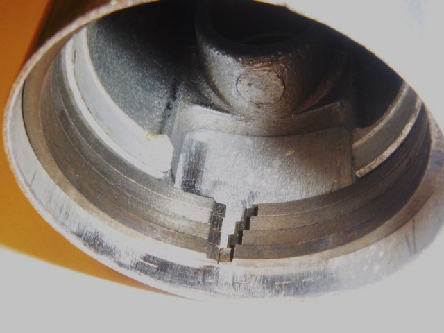
Break a ring, how not to: Two stroke pistons have little pins (stumps, bumps) in the piston ring grooves that prevent the rings from rotating. Knowing where each ring locating pin is, and aligning the ring gap over the pin during cylinder installation, is the key to not breaking the ring. 

If the piston is used the ring grooves will need to be cleaned (scraped). Use a piece of old broken ring as a scraper. Make sure the installed ring can rotate freely completely around and close fully in the ring groove.

Then make sure the bare piston will enter the cylinder. Then place each ring in the cylinder to make sure the gap is right, a tiny slit. Once both the piston and rings separately fit the cylinder, then proceed to install everything at once.

 Use both thumbnails to spread the ring just enough.  Place the ring gap over the ring gap pin. As the piston enters the bottom of the cylinder the slanted cut and the bottom of the cylinder begins to close the top ring. Look at the gap to make sure it is over the locating pin. Wiggle the piston slightly and push gently until the tom ring enters the cylinder and closes fully. Then repeat with the bottom ring. 

Measuring wear: A new piston ring is a the best tool to measure how worn a cylinder is. Conversely, a new cylinder is the best tool to measure how worn a ring is. To measure the wear of a ring, you need a perfectly round cylinder of a precisely known bore. A worn cylinder that has not been honed will still have it’s original new bore at the very top, above where the rings rub at. A new ring in a new cylinder should have a very small end gap of .004 to .008″. A worn but still OK cylinder with a new ring will have a gap of .0010 to .018″. A worn cylinder and ring both will have an end gap of over .020″(.5mm). A badly worn cylinder and/or ring will have a huge gap, over .030″(.75mm). You measure ring gap with a feeler gauge.

Classifying Jawa Rings

Classifying Piston Rings

Classifying rings: Rings get mixed up and are difficult to tell the size, unless a perfectly round cylinder of an appropriate size is available to place the ring in. If you try to squeeze a piston ring into a circle with just fingers, it inevitably becomes a very rounded polygon, or at best an ellipse. So the measurement becomes inaccurate. At right is how Myrons Mopeds’s Jawa piston rings were classified, using a piece of aluminum tubing with a tight fitting piston inside it to hold the tube round, and the test ring square. From top to bottom, 39.03 x 2.0, 39.28 x 2.0, 39.53 x 2.0, 39.78 x 2.0mm. Each ring increases in diameter by 0.25mm, so the circumference increases by Pi times that, or about 0.8mm. Here the inside of an old fishing pole tube is 39.78mm, perfect for the 3rd oversize 39.78 ring, on the bottom, with a gap of almost zero. Each gap is 0.8mm more because each ring is 0.25mm less diameter. It is important that the piston and ring fit the cylinder properly.   

Filing down: To make a ring slightly smaller, one of the two ring ends can be filed down, while preserving the shape. To reduce the size (diameter) by 0.20 mm, the end must be filed down by pi times that, 0.63 mm. When a filed down ring is installed in a cylinder smaller than it was designed for, two things change. The tension is greater, and the shape is slightly non-circular. So filed rings need a longer break-in period, to wear down the higher places. With 38 to 41 mm rings, the size can be reduced by 0.2mm with about 30 minutes of break-in, and by 0.5mm with about 2 hours of break-in. After break-in the rings have a mirror polish all around.

Why is the width not specified? Because the inner side of the ring does not touch anything. The ring has spring tension pushing it outwards, keeping the bottom (inner) surface from touching the bottom of the ring groove. So the ring width can be any amount, from about half the groove depth, to the groove depth. The exact ring width is not important. Exact ring height and diameter are important. 

Pistons

Two-stroke Piston Installation: Unlike a four-stroke engine, a two-stroke has holes in the cylinder wall, called ports. The ends of the rings are prevented from passing over any of the ports, by pins in the piston, inside or alongside the ring groove. A four-stroke piston does not have ring pins. Two-stroke ring pins often get overlooked, resulting in broken or damaged rings. See above about ring installation.

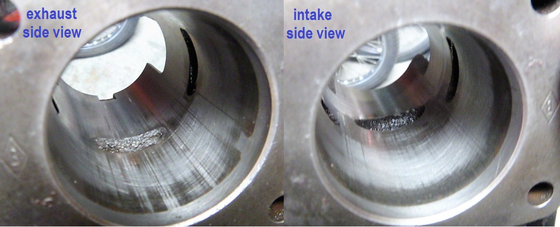
Pistons can be installed backward. Some do not matter which side faces forward or backward. But most do have a intake side (usually rear or up facing) and an exhaust side (usually forward or down facing). If it matters which way there will be a mark on the top of the piston, usually an arrow, on the exhaust side. Some Italian pistons say “SC” on the exhaust (scoria) side instead of an arrow.

There is a way to tell which way a piston faces regardless of the markings. This method is for when arrow on top is missing, or gets coated with black carbon, or if the piston is a substitute made for a different engine or cylinder. Remove the cylinder and piston and rings. Mark the top of the piston where the ring pins are. Place the piston in the cylinder at the bottom of the stroke, where the piston top is even with the exhaust port bottom. The angle of the piston pin needs to be the same as if it was on the crank. Now look straight up the cylinder wall from the ring pin marks for any ports. The ring gaps should never be closer that about 3mm 1/8″ from any port. If they they are then rotate the piston 180 degrees and see if that way works. If any ring end is allowed to pass over a hole, the engine will run for awhile, maybe 5 minutes to an hour. Then the ends of the ring will become rounded and the engine will loose compression.

Piston to cylinder clearance: It’s important that the piston fits the cylinder properly. An old messed up piston that fits correctly is better than a new piston that fits too loose or too tight. Too loose will be hard to start and weak. Too tight will seize up when hot. Often a cylinder needs to be bored out slightly to fit an oversize piston. Some aluminum cylinders have plated walls that cannot be bored out. The piston diameter, measured at the skirt, is a hair smaller than the cylinder bore.

The following piston/cylinder clearance limits are from the Puch factory service manual:

Puch “Lo-torque” nikasil plated aluminum (7-fin) cylinders:  Min .0008“(.020mm)   Max .0016“(.040mm)

Puch “Hi-torque” steel sleeved aluminum (8-fin) cylinders:  Min .001″  (.029mm)    Max .002“(.055mm)

Puch  “Magnum” steel sleeved aluminum (9-fin) cylinders:  Min .001″  (.029mm)    Max .002“(.055mm)

As the engine gets hot, the piston to cylinder clearance approaches zero. Besides “diam“, “upper“, “pin“, and “lower“, other things matter in piston compatibility. The ring pins must locate the ring gaps so they never pass over a port. The exhaust-side skirt must be long enough to cover the exhaust port at tdc. The intake-side skirt, on a piston port two stroke, controls the intake timing. Shorter skirt opens sooner and closes later. A longer intake skirt is one way some mopeds are restricted in power. Simply grind the excessively long piston skirt back to 30mph specification, but no farther, to de-restrict the piston. Puch, Tomos, Garelli are the main kinds that use longer pistons to lower the speed, for 25 and 20mph states or jurisdictions.  This list contains all pistons made by original equipment manufacturers, although most of them are no longer available. The not-available ones are listed for their information, such as speed versions or piston size choices. If you happen to have an unknown piston with or without a part number, you can identify what it is from this list by measuring it and looking for matching measurements. From all these specifications, perhaps a compatible piston can be found or adapted. 

Cylinders

Honing: There are two kinds of hones, solid and flexible, with different purposes.

1) A solid type adjustable flat-stone hone will shave off high spots and restore roundness. It is used first for when there is damage like melted aluminum stuck to the cylinder wall, or gouges, or just regular wear at mostly the top exhaust side. After a dozen rotations or so any high spots are revealed, because the stone does not touch the low spots or worn areas. This type of hone is useful for both diagnosing and restoring.

2) A flexible flat-stone or ball-stone will skip over high spots and not restore roundness. It is used last for lightly scratching the cylinder wall surface, and for rounding any sharp edges on the ports. Simple “finger sanding” with emery cloth is almost the same as flexible-ball honing.

Top is a flexible hone, ball type, 2″ (when new).
Bottom is a solid hone, adjustable, 1½-2″.
One of the flat stones is shown removed.

A worn Benelli G2 cylinder after solid-type honing.
Light areas are shaved. Dark (worn) areas are untouched.
Max wear zone is near the top where the pressure is most.
The very top does not wear because the rings don’t rub there.


Cylinder checking and honing:

1) Before honing, the used top ring is placed at the very top of the cylinder, where no wear occurs. The ring gap is noted, either visually or measured with a feeler gauge. If the cylinder has never been honed before, the ring gap at very top will indicate how much ring wear there is.

2) If a new ring is available, place it at the top and notice the ring gap. If the cylinder has never been honed it will have a very small gap, 0.004 – 0.008 inch (0.1 to 0.2 mm). That is only a little more than one human hair! Now place the ring in the maximum wear zone at the top of the ring travel. Compare the ring gap there. That tells how much wear the cylinder has since it was either new or last honed.

3) With just the ring installed squarely in the max wear zone, hold the cylinder towards a white wall or brightly lit background. Visually see if any light can get under the ring. This checks both the ring and cylinder for roundness. If the ring is new and is the correct size, this checks the cylinder for roundness.

4) The cylinder is honed briefly with a solid-type adjustable hone (not flexible). This shaves off high spots and exposes worn areas.

5) It is visually inspected for any deep grooves remaining, especially higher than the top of the exhaust port. If grooves and low areas remain, honing is repeated until most of the high areas are shaved off and only some low areas or shallow grooves remain. 

6) Solid-honing restores the condition of the cylinder wall, which is a good thing. But it also makes the cylinder bigger, which is a bad thing. The least amount of honing is best. So leave some patches of un-honed cylinder wall, like in the Benelli cylinder example shown above. When the engine first runs with new rings, the final polishing will occur.

7) After solid-type honing, use a flexible ball type hone to lightly scratch the entire surface, and to round off sharp edges of the ports. The hone is pulled and pushed in and out while rotating, to make a cross hatch pattern. The diagonal scratches help oil to get under the entire ring during break-in. This helps the new rings and cylinder wall to become polished like a mirror after the first few dozen miles of running.


Piston pin hole checking and Piston pin bushing reaming

On most 1960’s and 70’s small two-stroke engines, the piston swings on a bushing. Only some had needle bearings. By the 1990’s all small engines had needle bearings. A needle bearing can endure running without oil, but a bushing cannot. Upgrading to a needle bearing is a good thing, but it is often not possible with the same crank rod. Usually the rod hole needs to be bigger. With Puch, the 12 x 14 bushing has no needle bearing equivalent. The nearest needle bearing size is 12 x 15 (with 1.5 mm rollers). A 12 x 14 bearing would need 1.0 mm rollers, too thin and long to resist bending or breaking. So in most cases it is necessary to re-use or replace the bushing. Below is the procedure for checking, replacing, and reaming the piston pin bushing.
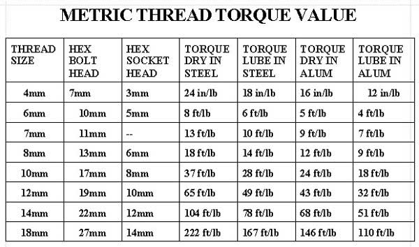


Brake Service

June 17, 2015

  1 Brake and Wheel Bearing Servicing

2 How to clean oil off the drum brake

moped brake service oil cleaning

Go buy a spray can of brake cleaner and a small can of straight acetone. First use acetone, rags and brushes to get most oil grime off. Then use brake spray to blast off what is hiding in the corners. Careful not to spray the center (that would flush MORE grease out). Use clean rags at the end.

Some oil can lurk between the aluminum hub and the steel sleeve lining the drum. It won’t come out until the hub is hot, either heated by torch, or when riding downhill with using the brake a lot. That can contaminate the new brakes. One way to heat the hub, is with the old brake shoes. After the hub is cleaned, the bike is rode with the old brakes, using them hard and often until the hub gets hot. Then the last oil comes out onto the old brakes. Then the hub is re-cleaned and new brakes are installed.


3 How to spread horse shoe brake springs

How to spread those nasty horseshoe brake springs: There are special spring spreading pliers made for this. Or this an easy to make tool that spreads it as the nut is tightened. The grooves at the ends hold it in place. Be careful, these springs store a lot of energy. Things can shoot like bullets.


4 How to fix sticking cable/drum brakes

First thing to do is put oil in the cable and on the handlebar lever moving parts. Lean the bike over and apply drops of 3-in-1 oil, so that it runs downhill into the rear brake cable. Apply one drop of oil on the outside of the brake plate where the brake cam shaft goes in. Operate the brake back and forth using your other hand to help the spring to return the cable. If it still sticks then disconnect the cable and feel the brake action and the cable action separately.

If the brake feels sticky, like at a certain point it “falls into a rut”, then the shoe plates have worn grooves in them, causing the sticking. If the brake cam sticks in many places, then remove the shoes, remove the brake cam shaft, clean and grease it and put it back. If it’s just the grooves in the shoe plates, then replace the brake shoes, or else, for most kinds, “flip” them by putting the right on on the left side and the left one on the right side. This makes the grooves go away.

Coil Spring Cable Assist 1 of 6

Coil Spring Cable Assist 2 of 6

Coil Spring Cable Assist 3 of 6


Wind the Tail Around

Thanks to Mopeds A Go Go for this amazing and useful trick!

As a last resort, sometimes an external helper spring  is needed to assist the internal springs in pulling the cable back. A very clever trick (originally from Mopeds-A-Go-Go in Westchester CA USA) is a way to add a coil spring onto any cable without any dissassembly whatsoever. Unbelievable? Imagine cliping one end off a coil spring so it has a tail that curved like the rest of the “threads”. That tail is wound around and around the exposed cable wire by rolling the coil spring over and over with your fingers. After the last thread, it will install completely and surround the braided cable wire. If the length is chosen right, by cutting the spring, there will be right amount of force or squeeze. Wow!


 How to put wheels on correctly


Puch Wheels Service

June 17, 2015

Puch wheels exploded view and notes


Bent Fork

June 17, 2015

How to spot a bent fork

This bike has a bent fork. Notice how the blue covering over the upper fork tube is not parallel with the black lower sliding tube. Also the grey accordian style fork boots are not parallel. All four locations, R-upper, L-upper, R-lower, L-lower, should be parallel, when viewed from the side, standing back a few feet or more. Sometimes things are blocking the view, like coverings on Motobecane forks, that must be removed to see the actual fork tube. In this blue LX in snow photo, only the left side appears bent. A photo of the opposite side would help. You need to sight from each side of the bike, to check for a bent fork.

A blind person can tell if a bike has a bent fork. With a straight fork, straight frame and good steering and everything else, you can walk your bike holding it by the seat, and leaning it ever so slightly to steer. When the fork is bent to one side, the bike will have to lean a little in order to go straight, or else it will tend to veer off to one side. After you practice doing this with your eyes open, try closing your eyes and doing it “by feel”. When the fork is bent straight back, with both tubes bent equally, the bike will ride straight and feel OK, with only slight subtle changes in steering behavior (quicker, quirkier).


How to Diagnose

June 17, 2015

1  How to Diagnose a Moped     

by Shaun Strahm, Jan 2008         This is a brief two-page universal diagnosis procedure. Details are omitted.


Engine: Compression, solidness, smoothness can be felt by hand. Good = solid & smooth. Bad =loose or rough.

Locate the magneto flywheel or the center part of the clutch wheel. That’s the crankshaft. It should turn freely with your fingers, except every turn it should require almost a whole hand to squeeze the air above the piston. It should spring back in both directions in the region from mid stroke to top. Removal of the spark plug allows you to feel only the magnetism in the flywheel, which can feel like compression. Compare the compression with and without your finger over the spark plug hole. With excellent compression you won’t quite be able to hold it all in and it will hiss and make a red circle on your thumb. That’s what over-100psi compression feels like. Low compression can be caused by several things, in order of severity: loose head nuts, decompression valve too tight or leaking, gummed-up stuck rings, worn or damaged rings, worn or damaged cylinder, loose brass wrist pin bushing, or loose wrist pin hole in piston. The decomp valve can be checked by removing the head, tipping it up the combustion chamber facing down, and filling liquid such as WD40 behind the decomp valve. None should leak past until you push it open with your finger. The piston and rings can be visually inspected by removing only the exhaust and looking up the exhaust port. Vertical lines across the rings and piston means it needs at least new rings and maybe a piston and cylinder. A solid black coating on the aluminum piston means the ring grooves are probably also black-coated, causing rings to stick and have low compression. In many cases the compression will be enough to run, but with some issues, in order of severity: needing a bigger idle hole in the carburetor to idle, idling badly, loss of power, making the spark plug get black and need frequent changing , dying out often at idle, even with over-rich idle mixture and a new clean spark plug.

Besides compression, the crankshaft bearings are checked simultaneously by turning the engine over by hand and feeling how solid and smooth it is. Brand new ball bearings feel completely smooth and silent, like a wet ice cube across a smooth countertop. Bad bearings have cavities and pits where the balls roll at, causing them to feel and sound rough, like there’s sand in them. Besides the two main ball bearings on each side there’s a center needle bearing in the big end of the rod. It’s part of the crankshaft assembly, which is expensive $100+, and requires disassembly of the cylinder and piston to isolate its motion and feel it by hand. An engine will run OK with rough bearings but will sound bad, like a blender or a garbage disposal. But there’s a catch. Along with the damaged bearings are also usually bad seals, the rubber rings alongside each crank bearing that seal in the two-stroke crankcase suction and pumping pressure. Leaking crank seals will cause the carburetor to need bigger jets to compensate for dilution of the gasoline-air with fresh air, and to have less power and die out often when idling. One way to check the seals is for one person to pedal the bike, turning the engine rapidly with the spark plug out and carburetor off, while the other person holds their finger over the intake manifold hole and feels how much suction there is. Good is when it’s hard to pull your finger off and it leaves a purple dome suction mark. Besides the seals, the cylinder base and the crankcase can also have compression leaks.

The next thing to check for is looseness of the piston and/or connecting rod. This can be done by lightly touching the top of the piston with the tip of a pen or pencil, through the spark plug hole. With the piston near top, wiggle the wheel back and forth slowly and feel the piston move along with it. There should be no detectable looseness. If there is, then disassembly is needed to tell if it’s the piston pin hole, rod little-end bushing, or rod big-end needle bearing.

The last thing to talk about is the first thing you notice. The engine is frozen and the crankshaft flywheel does not move at all. This happens often when the moped sits outside for a long time and rusts inside the engine, especially after being run without enough oil in the gas. The first step is to put penetrating oil in the spark plug hole and in the intake, then try to rotate the flywheel. If it’s just frozen because of tar, then it will melt away and be OK if it was already OK before it sat up. Mopeds stored outdoors are usually rusted solid and need crankshafts, pistons, and sometimes flywheels, cylinders, and whole engines. It’s ecommended to make a tool to hold onto the flywheel to get it to rotate first before disassembly. Sometimes it “wakes up” with just that. Other times it’s stuck tighter than 100 lbs hanging on a 3 foot bar, about the breaking point of the woodruff key. That’s when you remove the head and exhaust, raise the cylinder and see if it’s rusty in the crankcase or just the piston & cylinder.

Ignition: Does it have spark? Is it blue? Does it happen at the right time (17-25 degrees before top)?

Check for spark by removing the spark plug, plugging the wire on it, laying it on the metal of the engine or frame, and then rotating the engine (turning it over) while observing the spark plug gap. There should be little blue or lavender sparks making audible snaps, every time the wheel goes around. Having a fouled plug can falsify the test. The white porcelain insulator must be clean, dry and white to dark brown, not wet, black, silvery, or bridged with carbon balls. The corners of the electrodes should be sharp, not rounded, with a 0.020” gap, less than a car. When there’s no spark at all, more often than not, on ‘70’s US model mopeds Peugeot, Piaggio/Vespa, Garelli, Cimatti, Derbi, Tomos, and others, it’s a wiring problem with the brake light. The first thing to do is find out if there is a “secret” magneto wire that needs to be grounded. It’s the blue wire on most, except on Peugeot it’s black and on Puch and some Sachs it’s blue and black. With the external ground bypassed directly to ground the spark is re-checked. One more bypass is to disconnect the kill switch, in case it’s “off”. The kill switch grounds the coil wire to kill the engine. After checking the points-to-coil-only wire and coil-to-ground, what’s left is inside the magneto, usually dirty points and sometimes a shorted wire. You can see the points opening and closing through the windows in the flywheel. First determine which way it rotates by rotating the rear wheel and engaging the clutch. See if the arrow on the flywheel is correct. Then find top by feeling the piston through the spark plug hole. It’s hard to find the exact point. Now the points should be open fully. Go forward all the way around again. As the piston rises the points are closed until 20 degrees before top, or about 7/8 inch along the edge of the wheel, after that they’re open to a gap of .012 to .018 inch for about 90 degrees. The spark happens at the moment of opening. You can tell visually if the timing is close enough to run, if the points open a little before top.

Carburetion: Does it have gas? Is it getting through? Or does it have too much?

Once the engine has compression, both primary and crankcase, and it has spark at the right time, then all it needs is some flammable stuff mixed with fresh air. Moped carburetors are frequently crusty with tar or glaze from dried up gas and oil mix. It clogs the tiny holes the gasoline passes through and makes the float stick. Besides tar there’s usually some rust powder from the gas tank and maybe white zinc oxide from the carb itself rusting. So it automatically needs a
carburetor service or at least an inspection. For diagnostic purposes, a flammable spray such as starting fluid (ether), carb spray, or WD40 can be used to start the engine, with a wide-open-throttle no-choke carburetor or without a carburetor. Hearing it run for a few seconds until the spray is consumed is good way to quickly know if it will “live”.

Very often a moped will become flooded. This is a condition where excess gasoline and oil have built up, and not enough fresh air is getting in. The thing to do is to keep cleaning the spark plug with carb spray. Once it gets wet it becomes ineffective. Pedal starting rapidly with a dry spark plug, wide open throttle, no air filter, no choke. Once it starts popping you should keep the throttle wide open until it cleans itself out, in maybe 15 to 30 seconds. Healthy bikes can become flooded from leaving the choke on or lying over with the gas left on. Not healthy bikes can become flooded from gasoline leaking past the float, or from too big of a jet,  clogged exhaust, faulty ignition, low compression, or a little of everything. Removal of the exhaust really helps a lot. It’s often full of oil or black gasoline anyway. You have to start a flooded bike to know whether it will clear out after it runs awhile or whether it will keep getting flooded.

The test ride: Does the transmission work? Is it making full power? Are the frame, wheels, brakes and lights OK?

Now that the engine runs, a test ride is needed to learn what’s working or not. First the tires are aired. The wheels are checked for looseness. Cables, throttle, and chain are oiled. The forks and handlebars are checked for looseness and adjusted straight. When riding, see if it pulls to one side (bent fork), is wobbly (loose rear wheel, spokes or wheel bearings), oscillates (bent rim or lumpy tire), stops poorly (oil film or rust on brake drums), goes slow (clogged exhaust, timing way off, something rubbing). Ride it long enough, say 10-15 minutes, to let it wake up. Check the head light, speedometer light, tail light, brake light, horn, and speedometer. Finally, see if it goes full speed, usually 25-30mph.


All About Oils

June 17, 2015
Myrons favorite two stroke oil. For premix or injector.

Myrons favorite two stroke oil. For premix or injector.

Two StrokesMost older mopeds and motorized bicycles are two stroke engines that do not have motor oil in the crankcase. Instead the crankcase has a mist of gasoline with 2% or 4% two stroke oil blended in. The crankshaft and piston are lubricated by the gasoline mix. Two stroke oil is designed to be stable when mixed in gasoline, and to burn clean and not make black tar and carbon build up. Regular motor oil will work in a two stroke, but will leave a mess of tar in the engine and or gas tank.

Champion Synthetic Blend 2-Cycle Power Equipment Oil, with fuel stabilizer, is the two stroke oil that Myrons Mopeds recommends. It is a premium quality ashless motor oil for use in 2-cycle air cooled engines (with higher temperature demands). It combines Group II base oils and pure isobutene, rather than commonly used fragmented isobutene which can degrade faster at high temperatures. In addition, it contains several semi-synthetic additives providing excellent detergency and a dispersant to provide protection and performance. Super tough film, anti-foaming, anti-scuffing, fuel stabilizer, all beneficial.  

In a two stroke (2 cycle) engine, separate from the crankcase is the transmission case, which does have a pool of motor oil or automatic transmission fluid in it. The transmission oil or fluid needs changing every 2000 miles. Below is a chart showing what oil goes in what moped engine, and where to add it and check the level.

Four Strokes: Most newer mopeds and scooters are four stroke engines, like cars, with motor oil in the crankcase. The oil for those is the same as for cars, such as 10-40W. Four stroke oil is motor oil. But unlike cars, the transmission shares the engine oil, like most motorcycles. Motorcycle (non catalytic exhaust) motor oils contain ingredients that are beneficial, but harm the catalytic converter. Motorcycles, scooters, 4-stroke mopeds with catalytic converters should use ordinary car motor oil.  

Moped Trans Oil Chart

Moped Trans Oil Chart

Oil Specified in Owners Manual: Often the specified oil is obsolete. In ATF, the old “Type A” (non-Ford) went on to become Dextron (Type B)  in the late 1970’s, and then Dextron II (Type C and Type D), III, IV, V, and now “Dextron VI“, for most GM vehicles and pre-2004 Toyota automatic transmissions. 1970’s Tomos and Sachs mopeds specified ATF Type A. Tomos also specified motor oil 10W30. The old ATF “Type F” (Ford/Mercury) went on to become Mercon in 1987, as did “Type G” (Ford Europe), and then Mercon II,III,IV, and now “Mercon V“, for most Ford, Lincoln, Mercury automatic transmissions. 1970’s Puch and Kreidler mopeds specified ATF type F 

Type A versus Type F: Type A up till the 1970’s contained whale oil as a friction modifier. A modern friction modifier/reducer is glycerol mono-oleate. Type F contains no friction modifiers. Modern vehicles have nine current ATF versions: ATF+4, Mercon V, Mercon LV, Dextron VI, ATF DW-1, SP-III, Matic-S, Toyota ATF-WS, Honda DW (ZF). Any of these will work in a moped transmission. They are only slightly different. ATF Mercon V would be the safest to use, since it does not have friction modifiers. Friction modifiers are better for the gears and bearings, to reduce friction and extend life, because part of the molecule clings to metal and part is a long chain that slides over metal easily. What’s good for the metal parts may or may not be good for the clutch. This is a current area of investigation. 

Detergent versus Non detergent: Motor oils come with a detergent additive that keeps the dirt floating in the oil, so it can be removed by the oil filter. Non detergent motor oils allow the microscopic dirt particles to settle out. They are for engines and machinery that do not use oil filters but instead rely on manually removing the sludge from the bottom of the oil bath, as in machine shop equipment and small gasoline engines. Some rubber parts can get damaged from the detergent in the motor oil, in particular the Garelli 1-speed and 2-speed centrifugal solid rubber clutches. Garelli, Morini MO-1 and MO-2 call for 30W non detergent (ND), while Batavus/Trac, Demm, Derbi, Indian, Minarelli, Morini M-1 call for motor oil 30W, 40W or 10W40. See above chart. 


Threads

June 17, 2015

Metric Nuts and Bolts

Metric thread nuts and bolts are used in products made in every country in the world, except for the USA. 

Size: Metric bolts (male thread) and nuts (female thread) are named by the outer diameter of the male thread. The name begins with a capital M and the size. So an M4 bolt is a 4 mm metric, M5 is 5mm metric.

Pitch: After the size is the thread pitch, which is the width of each thread. A 1.0 pitch is 1mm wide, so 10 threads are 10mm. A 1.25 pitch is 1.25mm wide, so 10 threads are 12.5mm. A 1.50 pitch, 10 threads are 15mm. A metric ruler laid alongside a bolt, can measure the length of 10 threads. Then the thread pitch is calculated by dividing by 10.

Length: After the pitch is the length, in millimeters. The length of a bolt does not include the head. It is the length of the shank, from the base of the head to the end. So a M6 x 20 hex bolt has a 20mm long shank. But counting it’s 5mm tall hex head, the total length is 20 + 5 = 25mm. 

Metric Bolts


Myrons Pin Cushion


Four views of the Myrons pin cushion, used for thread identification. The orange color labels are American threads. The white labels are metric. Some threads are very similar and require screwing a reference nut onto the reference bolt and the test bolt. Some threads are different enough to recognize by eye, after getting familiar with the sizes.


Thread Repair

Read all about motorcycle thread repair http://www.dansmc.com/bolts3.htm

Read all about bicycle thread repair: http://www.parktool.com/blog/repair-help/basic-thread-concepts.>


Tightening Torques

Different size bolts under different conditions require different tmetric-torque-valuesightening torques.


Lubrication

Lubrication helps the behavior and performance of threads. Some new nuts and bolts, mostly from China, will actually fail without lubrication. The threads will bond together when tightened fully. Always wipe grease or drip oil onto new or used threads, especially inexpensive soft metal ones.

When threads fail or get “stripped”, they either “shear” off into thin curls, or “smear” off, where the tops become lower and the valleys become higher. 


Tire Mounting

June 17, 2015

This is not a complete set of instructions. You can read how to change a moped tire in most manuals. This is an additional item, very often overlooked that needs mentioning.

Left,  a tire has just been mounted on the rim. Before air is added, the area near the valve stem is checked. Sure enough, the tube is pinched between the tire and the rim. If ignored, this will cause a bulge in that area.

Right, the same tire after pushing the valve stem up inside the tire. Now the tire will be straight when inflated. Pushing the valve stem inside the tire before the final mounting will also make the mounting easier, since the pinched inner tube is making the tire tighter on the rim on the opposite side. When your tires are mounted correctly, smooth roads will not feel like bumpy ones, and your bike will feel solid, smooth, and more enjoyable.


It often happens that new moped tires do not automatically go on straight.
Tires that fit tight offer increased safety because they stay on the rim during a flat.
But a tight fitting tire is more difficult to install.
The causes are almost never the tire itself. Here are possible causes of a “lumpy” tire.
1) The rim has tape or the rubber strip covering the sides where the tire seats at.
    The rim strip normally only covers the center of the rim.
    Remedy is to cut or remove the tape or strip from the sides, so it only covers the center.
2) Part of the inner tube is pinched between the tire and the rim, usually at the valve stem.
    This happens when the valve stem is not pushed outward before first adding air.
    The inner tube under the tire makes it bulge at that spot.
    Remedy is to let the air out completely. Pull the tire back and look under it.
    The inner tube should not be visible. If it is, push it up inside the tire.
3) Some tires are stubborn and need help to climb up onto the rim seat.
     Remedy is lubrication and increased air pressure.
     With air out, squeeze and pull on the tire to shift it’s position.
     Then add air, and check the result. Often several tries are necessary.
     Sometimes at the shop we have to use up to 100 psi to “seat” a 35 psi tire.

Seized Engine

June 17, 2015

A seized engine is when the crankshaft, rod, and piston are frozen solid and cannot move. You try to pedal start it and it acts like a brake when you pull in the start lever (on a manual starting clutch type), or when the automatic starting clutch engages. It never makes that chug chug chug sound of the piston going up and down.

Here are the steps to diagnose and/or recover from a seized engine.

1. Spray WD40 into the spark plug hole. This will get solvent to the piston top and cylinder wall above the rings. If the piston is just stuck with tar from sitting, this will dissolve some of the tar and maybe unfreeze the engine.

2. Spray WD40 into carburetor (after removing the air filter) with throttle held wide open. This will get oil into the crankcase and lower part of the piston and cylinder, below the rings.

3. Locate the flywheel. Some bikes it’s on the left and some it’s on the right. The magneto flywheel on a moped is a 4 or 5 inch wheel that has magnets inside it. Most have wide holes that allow adjusting the points. The flywheel is attached directly to the crankshaft. It is crucial to not confuse the clutch wheel (which turns with the rear tire) with the flywheel (which turns with the engine). Motobecanes and Peugeots have exposed “wheels” on both sides on the engine.

4. Try to rotate the flywheel with both hands. If it moves, try going back and forth, each time a little more, until it goes all the way around. Then spray more WD40 in and go around again many times. When it’s loose enough, switch to pedalling to rotate the engine faster than by hand. When it’s finally free, it will not feel tight anywhere (with the spark plug removed). A normal flywheel that’s “free” should move in a full circle with one strong finger. If it takes a whole hand then it’s “tight”, not “free”. 

5. Determine what is stuck. A small screwdriver in the spark plug hole is used to feel the top of the piston. When just the piston is stuck, the crank will move a tiny bit back and forth, but the top of the piston will not move at all. When something like a loose screw or piece of debris gets stuck in the flywheel, the flywheel might move free within a range. Then the top of the piston will move with the crank. When neither the piston nor flywheel moves at all, then remove the flywheel and try to rotate the crank. If the naked crank is does not move, the engine is stuck internally, and the flywheel will then need to be put back on tight to continue the unfreeze process. If the crank and piston move free, then the flywheel is rubbing or sticking somehow. That can be caused by several different things each with a different remedy.

6. Find or make a tool to hold onto the flywheel, once you’re sure it’s stuck internally. Be careful to not allow the tool to damage the coils or wires behind the flywheel. Apply a rotation torque of, perhaps, 150 ft-lb for an 8mm crank nut, or 200 ft-lb for a 10mm nut crankshaft. These are estimates only. Be advised that too much torque can shear off the woodruff key and/or damage the crankshaft and/or flywheel woodruff key groove, or even break the crankshaft (possibly $500 damage). Applying high torque is risky but beneficial. 

To be continued …